4. Referto Optional Welder for a description of the
welder controls.
The Model 8020 band saw is equipped with a two-
speed gearbox. The shift lever is located on the front
of the band saw. Shift positions are L (low) and H
(high).
The Model 8120 band saw is equippedwith a three-
speed gearbox. The shift lever is located on the front
of the band saw. The shift positions are L (low), M
(medium), and H (high).
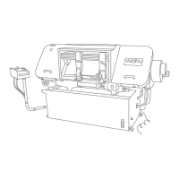
Optional Blade Welder
An optional blade welder is available on the vertical
band saw. The welder has all the features required to
cut, weld, and anneal the saw blade.
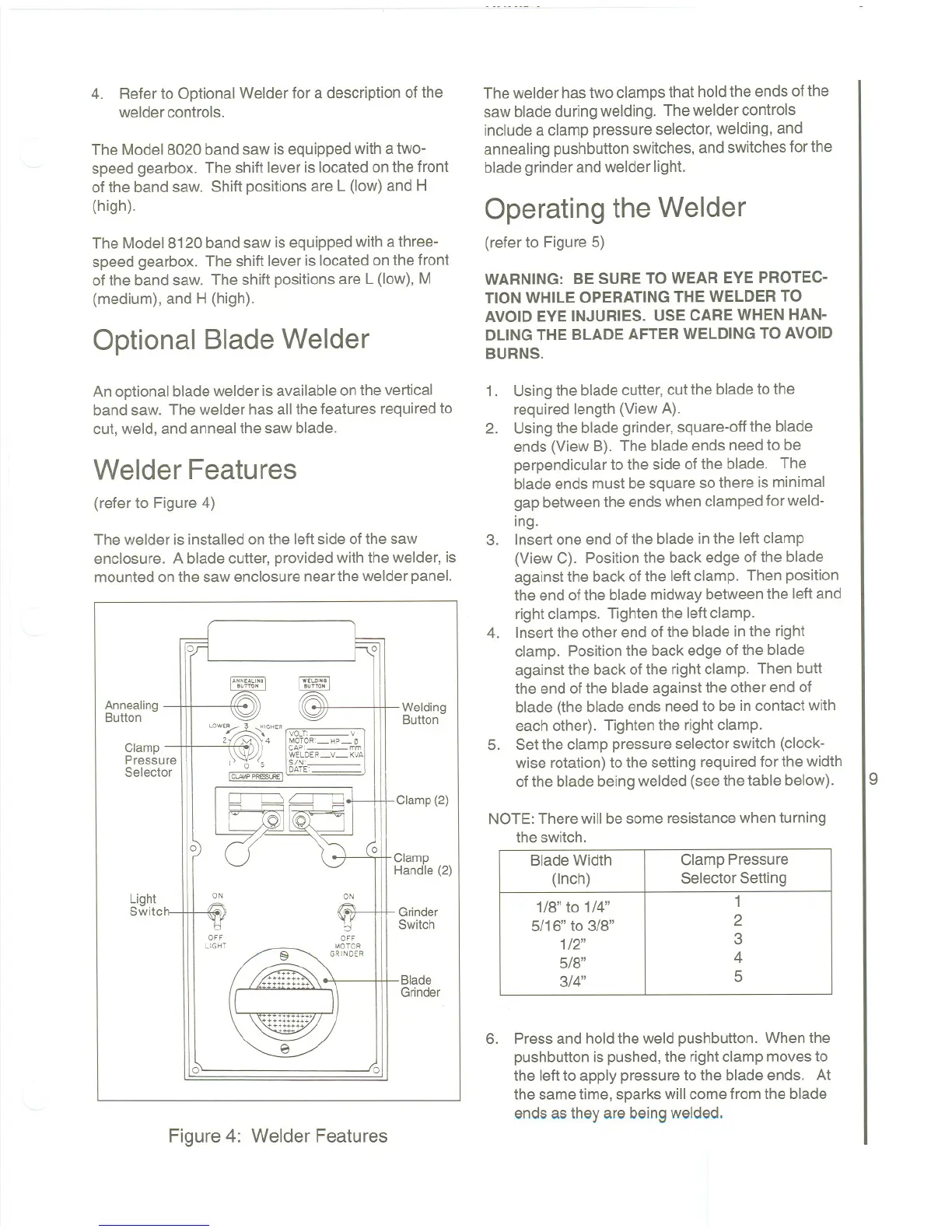
Welder Features
(refer to Figure 4)
The welder is installed on the left side of the saw
enclosure. A blade cutter, provided with the welder, is
mounted on the saw enclosure near the welder panel.
0 0
'"''''''
"Tro,
Welding
Button
Annealing
Button
Clamp
Pressure
Selector
LOWE/::
~
H'GHER
[
VOLT'- Y
2~ 4 MOTOR'-HP_~
\\'::Jf~ ~fLDELy_~w.1
I 0 5 5~~~'
IClA'.\P P"""LRE I
Clamp (2)
0
01,
Clamp
Handle (2)
Light
Switc
ON
ON
Grinder
Switch
OFF
LIGHT
Blade
Grinder
0
0
Figure 4: Welder Features
The welder has two clamps that hold the ends of the
saw blade during welding. The welder controls
include a clamp pressure selector, welding, and
annealing pushbutton switches, and switches for the
blade grinder and welder light.
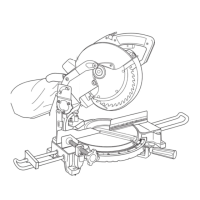
Operating the Welder
(refer to Figure 5)
WARNING: BE SURE TO WEAR EYE PROTEC-
TION WHILE OPERATINGTHE WELDER TO
AVOID EYE INJURIES. USE CAREWHEN HAN-
DLINGTHE BLADE AFTER WELDING TO AVOID
BURNS.
1. Usingthe bladecutter,cut the bladeto the
required length (View A).
2. Usingthe bladegrinder, square-offthe blade
ends (View B). The blade ends need to be
perpendicularto the side ofthe blade. The
blade ends must be squareso there is minimal
gap betweenthe endswhen clampedfor weld-
ing.
3. Insert one end of the blade in the left clamp
(View C). Positionthe back edge of the blade
against the back of the left clamp. Then position
the end of the blade midwaybetweenthe left and
rightclamps. Tighten the leftclamp.
4. Insertthe other end ofthe blade inthe right
clamp. Positionthe back edgeof the blade
against the back of the right clamp. Then butt
the end ofthe bladeagainst the other end of
blade (the blade ends needto be in contact with
each other). Tightenthe rightclamp.
5. Setthe clamp pressureselector switch (clock-
wise rotation)to the setting requiredfor the width
of the blade beingwelded (see the table below).
9
NOTE: There will be some resistance when turning
the switch.
6. Press and hold the weld pushbutton. When the
pushbuttonis pushed,the rightclamp movesto
the leftto apply pressureto the blade ends. At
the sametime, sparkswill comefrom the blade
ends as they are beingwelded.
Blade Width
Clamp Pressure
(Inch)
SelectorSetting
1/8" to 1/4"
1
5/16" to 3/8"
2
1/2"
3
5/8"
4
3/4"
5