Do you have a question about the Wintriss SmartPAC PRO and is the answer not in the manual?
Details the standard operational features of the SmartPAC PRO system.
Details the DiProPAC option for die protection sensor monitoring and fault detection.
Describes the ProCamPAC option for programmable cam timing control.
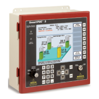
Covers the touch screen, numeric keypad, and on-screen keyboard interface.
General guidelines for proper installation, including wiring and grounding.
Detailed steps for installing the resolver assembly for crankshaft positioning.
Guide for connecting AC power wiring to the SmartPAC PRO unit.
Instructions for connecting 24 VDC power supply to the SmartPAC PRO.
Wiring procedures for emergency-stop, top-stop, and input check circuits.
Steps to install or upgrade DiProPAC or ProCamPAC optional modules.
Instructions for connecting DiPro die protection sensors via the DSI 2 interface.
Guide for wiring ProCamPAC programmable cam channels.
Procedure to zero the resolver, essential for accurate timing.
Instructions to set the zero position for the resolver.
Guide for installing the optional position sensor.
Final checks to ensure proper unit functionality before operation.
Manages tools: view, edit, create, copy, delete, and load tools.
Procedure for creating a new tool setup.
Procedure for loading a previously created tool for operation.
The menu for programming individual tool settings.
Initialization, programming, and use of ProCamPAC programmable cams.
Programming maximum and minimum speed limits for tools.
Adjustments to counter settings, including presets, in Run Mode.
Using DiProPAC features and adjusting sensor signals in Run Mode.
View press stopping time, limits, and perform stop-time tests.
Procedure to measure press stopping time for calculating the stop time limit.
Test to set safety distance for guarding devices based on stopping time.
Formula for calculating safety distance based on stopping time and standards.
Adjusting programmed speed limits for tools in Run Mode.
Procedure to load a new tool in Run Mode.
Sets how die protection sensors are enabled (Manual, Auto by Tool, Auto by Sensor).
Programming die protection sensors within Program Mode.
Adjusting sensor enable modes for specific tools in Program Mode.
Guide to configuring sensor parameters like enable mode and type.
Procedure for assigning names to each sensor.
Specifies strokes before sensors auto-reenable after a DISABLE command.
Sets strokes to re-enable individual sensors after a DISABLE command.
Allows selection of sensor type (Red, Yellow, Green, etc.).
Specifies how the press stops when a die protection sensor detects a fault.
Determines the critical angle for Smart Stop to decide between E-Stop/Top Stop.
Sets the timing window for green sensor actuation to prevent stop signals.
View sensor status, enable/disable all sensors, or turn selected sensors On/Off.
Manually enable or disable sensors in Run Mode.
Overview of the ProCamPAC module for controlling auxiliary functions.
Setting parameters for Auto Advance timing based on press speed.
Programming ProCamPAC sensors and settings within Program Mode.
Programming up to 8 or 16 cam channels.
Adjusting timing for programmed cam channels in Run Mode.
Explains messages related to counter presets being reached.
Details messages related to resolver, input circuit, and brake monitor faults.
Explains messages indicating tool loading or internal SmartPAC PRO issues.
Documents fault messages related to green, red, and yellow sensors.
Steps to initialize the PM Monitor before use.
How to view and modify PM alerts and status in Run Mode.
Steps to load new firmware onto SmartPAC PRO from a USB disk.
Details automatic and manual downtime reporting features.
Configuring downtime reporting settings on the Set Communications Menu.
Enabling and configuring downtime reporting features.
Documenting scrap counts and adjusting good parts count for SFC.
| Model | SmartPAC PRO |
|---|---|
| Manufacturer | Wintriss Controls Group |
| Connectivity | Ethernet, USB |
| Data Logging | Yes |
| Output Voltage | 24 VDC |
| Type | Press Automation Controller |
| Inputs | Analog, Digital |
| Outputs | Analog, Digital |
| Die Protection | Yes |
| Tonnage Monitoring | Yes |
| Automation Control | Yes |
| Communication Protocols | Ethernet/IP, Modbus |
| Control Type | Programmable |
| Communication Ports | Ethernet, USB, Serial |
| Operating Temperature | 0°C to 50°C |
| Storage Temperature | -20°C to 70°C |