15 / 47
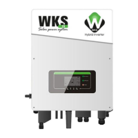
Step 2 Insert crimped PV positive and negative power cables into corresponding PV connectors
3. Positive connector 4. Negative connector
Fig. 8 prepare PV positive and negative connectors
Step 3 Make sure the DC voltage of each PV string is less than 600V DC and polarities of PV power cables are
correct. Insert the positive and negative connectors into WKS I inverter until you hear a "click" sound, as shown in
Fig. 9.
1. Bayonet
Fig. 9 Connect PV connectors
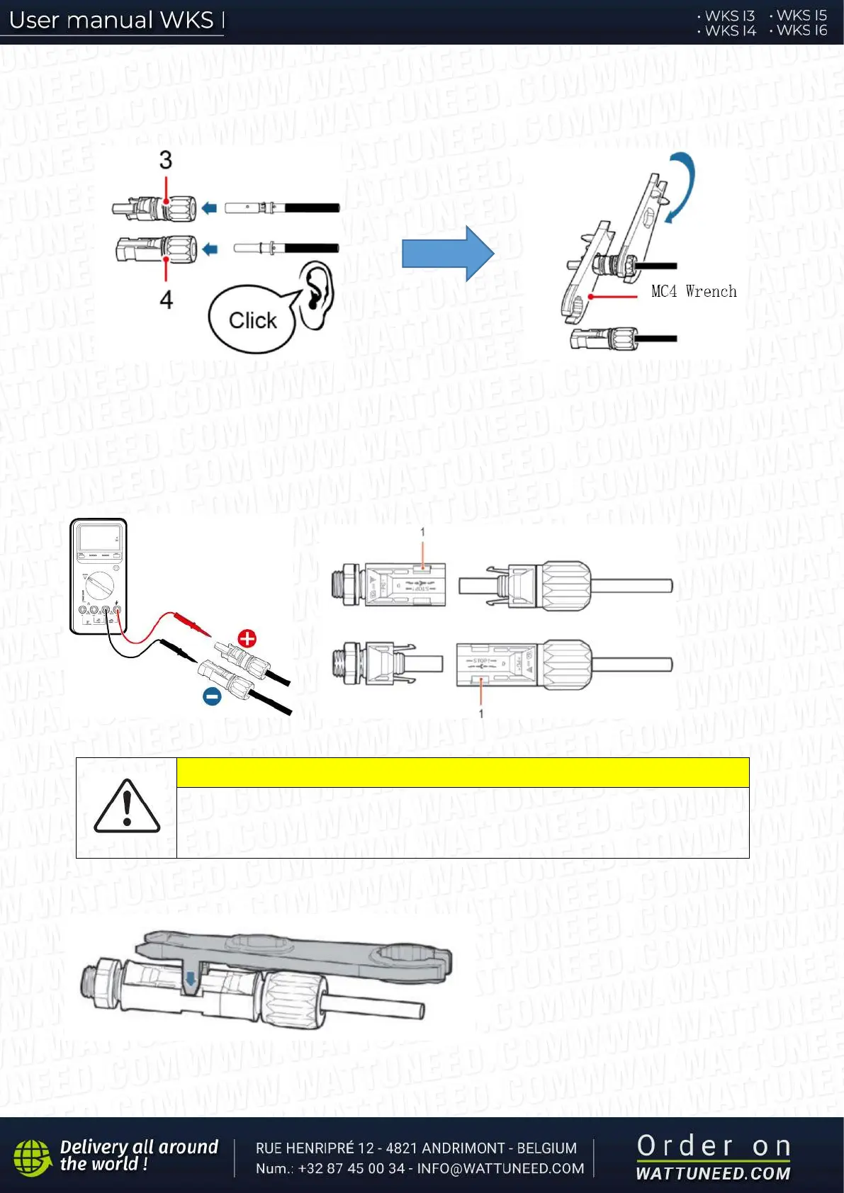
CAUTION
Before removing the PV positive and negative connectors, ensure that the DC
SWITCH is OFF.
Follow-up Procedure
Use a MC4 wrench to disconnect PV
connectors, as shown in Fig. 10.
Fig. 10 Disconnect PV connectors