Service 24
2.8.1 CAN bus
Communications between the front panel and the power stage make use of the CAN bus. Depending on the machine equipment level, other component assemblies may
be connected to the CAN bus:
I/O Board AutoClean
Cup sensor
Sirup power stage
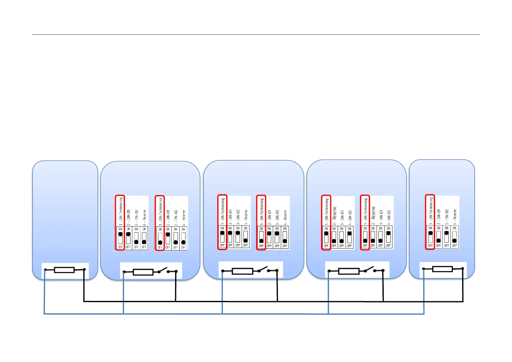
To prevent reflections and the resulting malfunctions on the CAN bus, it is necessary to terminate the CAN bus with a 120 Ohm terminating resistor at the start and end
points. The terminating resistors for the component assemblies indicated can be switched ON or off via the DIP switch. If one of the component assemblies that
communicates via CAN bus is replaced, then the correct DIP switch setting must always be checked.
When retrofitting a cup sensor, the DIP switch settings on the machine power stage must be adjusted.