3064458_201811
55
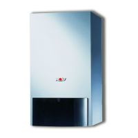
Fig: Gas combination valve
Fig: Test ports
CO
2
setting at lower
load (zero adjusting
screw)
CO
2
setting value
at upper load
23. Changing the gas type
1
2
4
6
7
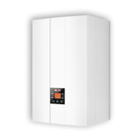
Fig: Control unit buttons
5
B
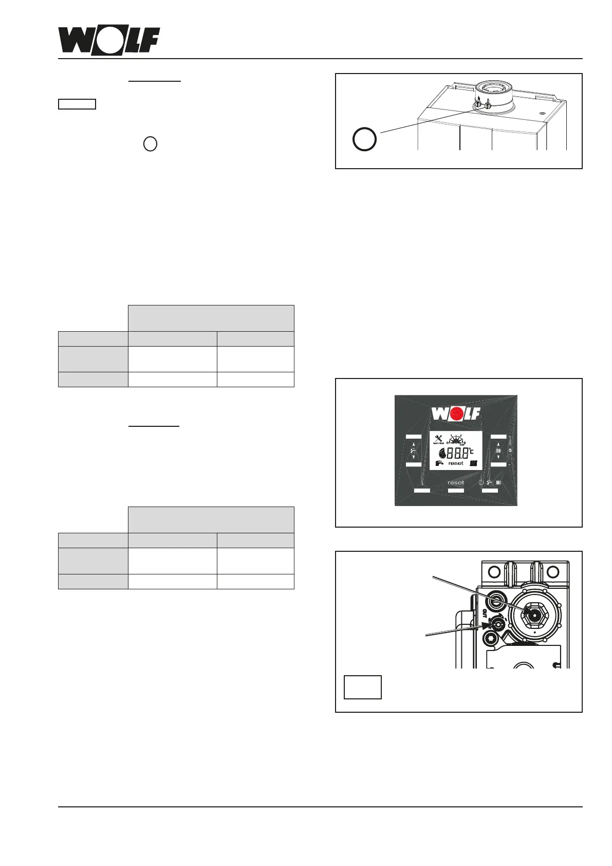
Flue gas test port
Do not remove the screws, otherwise it
will no longer be possible to adjust the gas
combination valve.
Please
note
CO
2
setting at upper load
When the test port is open, ue gas can
escape into the installation room. There is a
risk of asphyxiation.
1. Remove screw B from the right hand test port.
2. Open the gas ball valve.
3. Insert the test probe.
4. Activate emissions test mode (see control unit).
5. Approx. 20 s after the burner start, check the CO
2
content with the CO
2
tester. If required, adjust with
the zero point screw in accordance with the table.
- Clockwise rotation (-) – lower CO
2
content.
- Anti-clockwise rotation (+) – higher CO
2
content.
FGB / FGB-K
appliance open at upper load
Gas type CO
2
in % O
2
in %
Natural gas
E/H/LL
9.1 % ± 0.2 % 4.5 ± 0.3 %
LPG P 10.2 % ± 0.2 % 5.4 ± 0.3 %
CO
2
setting at lower load
1. Activate emissions test mode and
press DHW key - (2)
- Clockwise rotation – higher CO
2
content.
- Anti-clockwise rotation – lower CO
2
content.
FGB / FGB-K
appliance open at lower load
Gas type CO
2
in % O
2
in %
Natural gas
E/H/LL
8.9 % ± 0.2 % 5.0 ± 0.3 %
LPG P 9.8 % ± 0.2 % 6.0 ± 0.3 %
2. After completing the work, ret the casing cover
and check the CO
2
values with the appliance
closed.
The boiler is correctly adjusted when the CO
2
values correspond to those in table
"25. Testing the combustion parameters".
3. Optionally, a change to the upper load range can be
made by pressing the hot water button (1).
4. Disable emissions test mode (press key 4). After
the test has been completed, switch the appliance
off, remove the test probe and close the test port.
Ensure the screws/gasket are tight/seated rmly.
Please note