SETUP & OPERATION
Planer/moulder setup
3
3-1 EGdoc021023
SECTION 3 SETUP & OPERATION
3.1 Planer/moulder setup
IMPORTANT! Before starting to use the planer/moulder you have to
meet the following conditions:
Set up the planer/moulder on firm, level ground and level the planer/moulder. Secure the
planer/moulder to the ground to prevent moving during operation. A cement pad with 8-10
mm diameter anchor bolts is recommended.
Unscrew the feet. Screw the optional maneuvering wheels to the outer holes in the machine
body. The maneuvering wheels must be locked before starting work.
Indoors the planer/moulder can be operated with the sawdust collection system only.
The planer/moulder can not be operated when it is raining/snowing and in case of rain or
snow the sawmill must be stored under roof or indoors.
The planer/moulder can be operated in temperature range from -15
o
C to 40
o
C only.
The illumination at the operator's position should be at least 300lx
1
.
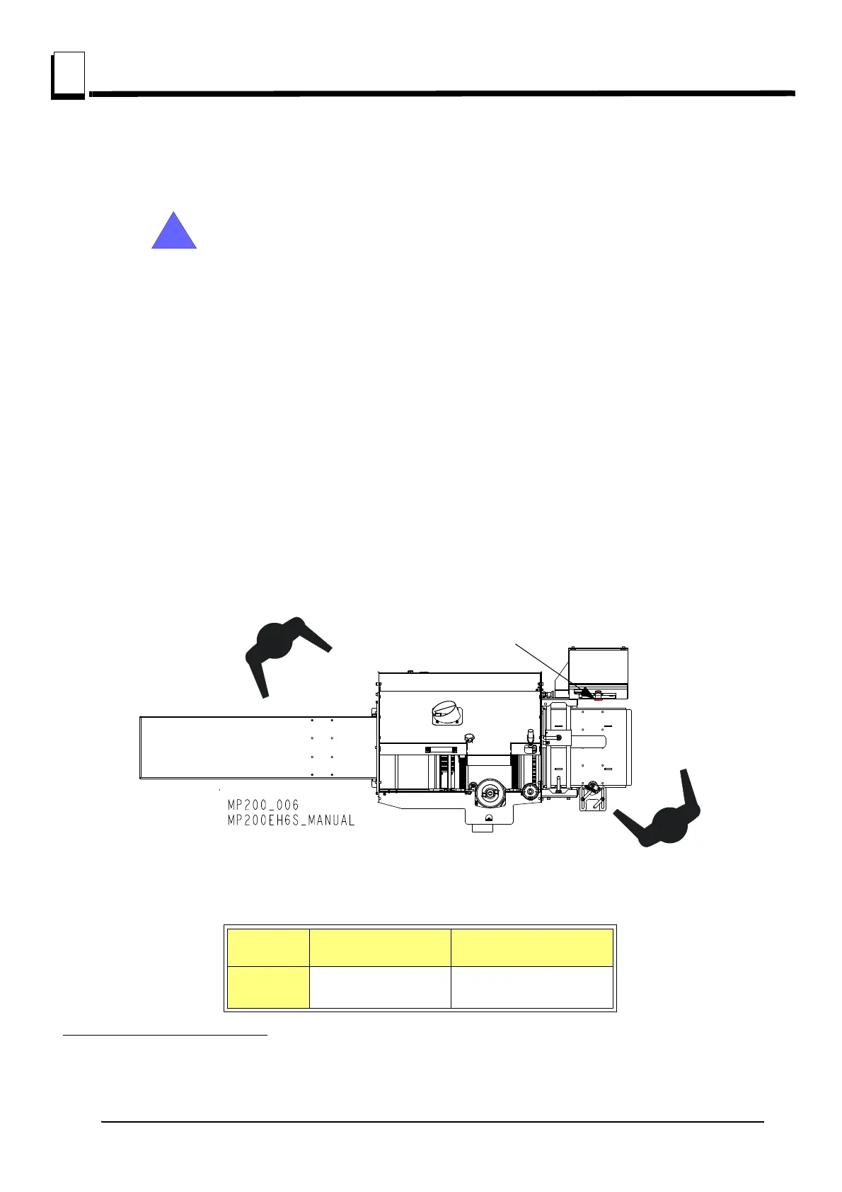
The planer/moulder’s operator position and E-Stop safety buttons location are shown
below.
See table 3-1. Have a qualified electrician install the power supply (according to EN 60204
Standard). The power supply must meet the specifications given below.
1. Light source can not cause stroboscopic effect.
3-Phase
Volts
Fused Disconnect
Switch
Suggested Wire Size
400 VAC 14 A
1.5 mm
2
up to 15 m long
TABLE 3-1