SETUP & OPERATION
MP200 planer/moulder operation
3
3-3 EGdoc021023
3.2 MP200 planer/moulder operation
3.2.1 Control panel
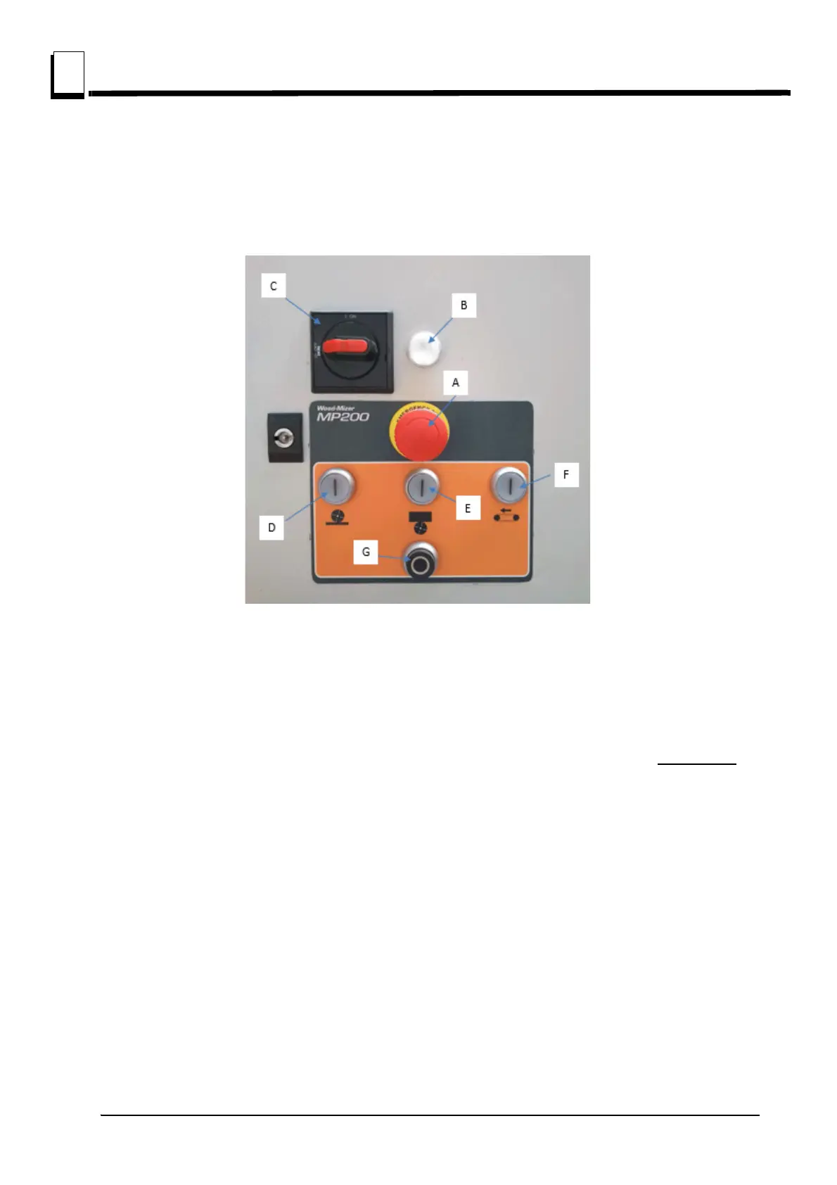
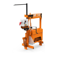
See figure 3-1. MP200 planer/moulder controls are shown below:
Top red button (A) - the emergency stop switch, which disconnects power to all functions. When the
emergency stop switch is pressed, it must be released before restarting the planer/moulder (turn
right).
Under the emergency stop switch there is an indicator light (B) which indicates that the power is on.
When replacing knives and servicing, the power On/Off switch (C) must be in the off position.
Check
if indicator light (B) is off.
The white buttons (D, E, F) start the planer's motors. The black button (G) stops the planer's motors.
The button's function:
Starting the horizontal cutter (D)
Starting the side, vertical cutter (E)
Starting the feed motor (F)
Stop all motors (G).
FIG. 3-1