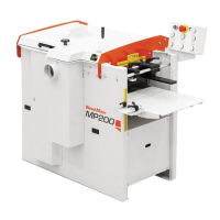
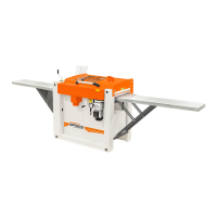
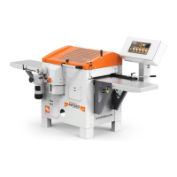
SETUP & OPERATION
Side cutter
EGdoc021023 3-8
3
Spacer5 mm
Washer set (0.1 – 2.0 mm)
To remove the planing knife from the side cutter, use 4mm allen wrench (supplied) to loosen lock
screws are recessed into the cutters.
The height settings for tongue and grooves:
When tongues and grooves need to be moulded, it is important that they are made opposite one
another, i.e. at the same height above the planing table. Remove the cutter from the spindle (see
above under the Disassembling heading).
Decide how the board should look. E.g. 8 mm above the groove, 6 mm groove and 7 mm below
groove.
Assemble the molding knife and tighten the socket head screw that hold the knife properly.
Place the cutter on the spindle without any spacers.
Measure the distance between top edge of the bottom knife and planer/moulder table.
If the cutter is 40 mm and the groove (6 mm in this example) is in the middle of the knife, the height of
the knife above the groove is 17 mm.
When the cutter is preset, the height of the knife above the table must be 30 mm (7 + 6 + 17 = 30
mm). If, for example, the height of the knife above the table is measured to 15.2 mm, the cutter must
be raised 14.8 mm (0.58") (15.2 + 14.8 = 30 mm).
Follow the procedure below:
Remove the cutter.
Use spacers to the desired thickness (14.8 mm in this example) and thread them onto the
spindle.
Place the cutter on the spindle and tighten the lock screw. Be sure the cutter can rotate freely.
Repeat these steps with the groove and tongue knife, to set it at the same height above the
table.
Plane the small, test board to check if groove and tongue are on the same height.
Or set the knife at any height and run the test planing. Measure and set the knife on the desired
height.
IMPORTANT! Spacers must be also above cutter to fix it on the
spindle. Add few spacers, which are not used for height setting. The
thickest spacer should be on the top and be several millimeters above
the lowest threads of the threaded bar. Next tighten properly nuts on
the threaded bar.