Setup
Setting the movable side cutter head
Setup doc050624 3-26
3
LOCK THE CUTTER HEAD IN POSITION
Place the large spacer rings above the cutter head. Only the treaded potion of the shaft
should be visible.
CAUTION! If the spacer rings are not stacked properly, the cutter head
may spin on the shaft, causing the shaft to become scarred and dam-
aged.
The top nut should then be replaced on the top of the shaft using two open-end wrenches
– one to hold the shaft, and one to tighten the nut. (See figure 3-16
.)
Setting the movable side cutter head
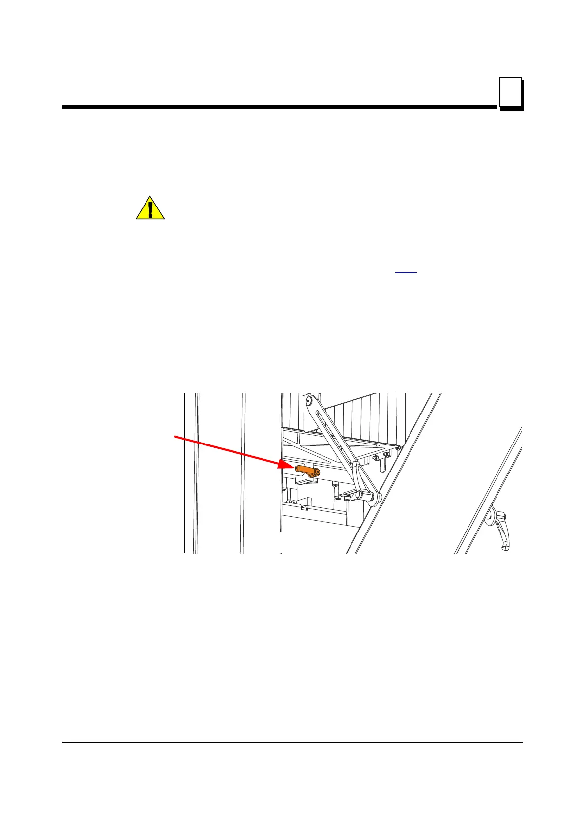
The movable side cutter head has a locking bolt under the table, on the outfeed side.
Loosen the movable side cutter locking bolt by the handle.
See Figure 3-20.
Use the crank on the front of the unit to move the side cutter in or out to the desired loca-
tion to cut the left side of the board.
FIG. 3-20
OUTFEED VIEW
Movable cutter head
locking bolt handle