Manual 35086 ProTech-GII with Math Functions
Woodward 118
b. The “Test Time Remaining” counter will be displayed and will begin counting down.
Note: If the “Simulated Speed Timer” setting is not configured for greater than zero, an
immediate timer expiration occurs, inhibiting display of the timer.
5. Press the “Value Up” soft key to increase the frequency generator’s simulated speed level above the
“Overspeed Trip” setpoint.
6. If the simulated speed signal is raised above the trip point, the local “Trip Relay” output will step to a
tripped state.
a. If the “End Test” soft key is pressed before the simulated speed is taken above the Overspeed
Trip setpoint, confirmation prompts will be displayed. After confirmation, the module will revert
back to the “Start Test” screen and also switch the local input speed channel back to sensing
actual rotating equipment speed.
b. If the “Test Time Remaining” timer expires before the simulated speed is taken above the
“Overspeed Trip” setpoint, the Screen Message, “Test Time Expired”, will be displayed and also
switch the module’s input speed channel back to sensing actual rotating equipment speed.
7. Issue a Reset command from the module front panel, discrete input, or Modbus communications port
to reset the module’s output Trip Relay back to a non-tripped state. The input speed channel will be
sensing actual rotating equipment speed again.
8. Users can alternatively view the “Overspeed/Acceleration Log” screen to verify sensed tripped
speed, maximum speed sensed during the event, sensed acceleration at trip point, and maximum
acceleration sensed during event.
See “General Testing Notes” below for information on related messages and their meaning.
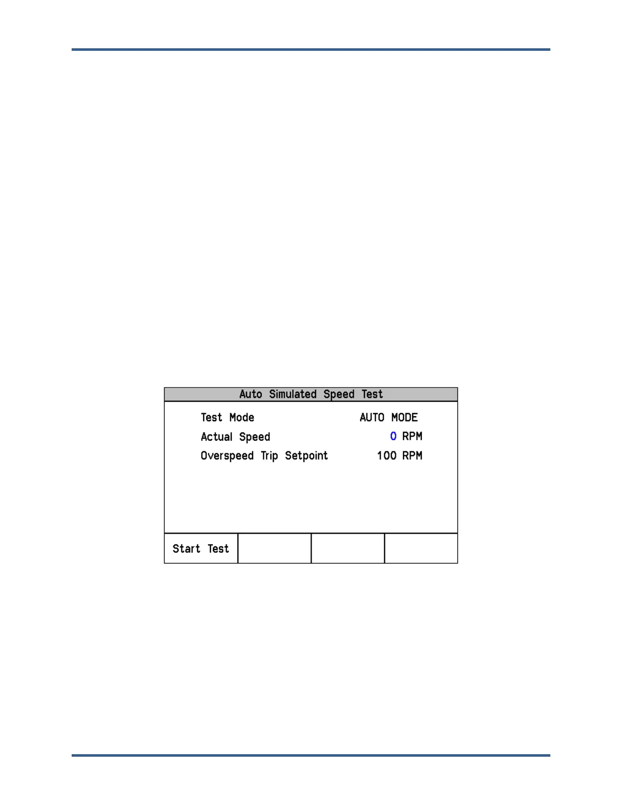
Auto Simulated Speed Test
Figure 6-6. Auto Simulated Speed Test Screen Example
Test Mode: Displays the test mode (AUTO MODE).
Actual Speed: Displays sensed actual speed.
Overspeed Trip Setpoint: Displays the Configured Overspeed Trip setpoint.
This test switches the module’s internal frequency generator into the module’s input speed channel and
sets the frequency to 100 RPM below the module’s “Overspeed Trip” level setting. This test then
automatically raises the module’s frequency generator’s simulated speed at a rate of 10 RPM/second
until the Overspeed Trip function issues a trip command to step the module to its trip state. This test
validates operation of the module’s input speed sensing circuitry, overspeed trip function, and output trip
relay.
 Loading...