Manual 35086 ProTech-GII with Math Functions
Woodward 44
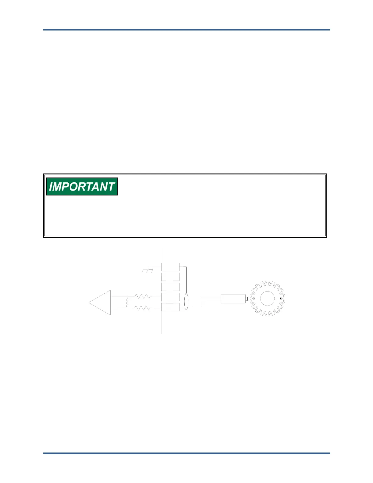
A passive MPU provides a frequency output signal corresponding to turbine or equipment speed by
sensing the movement of a gear’s teeth past the MPU’s pole piece. The closer the MPU’s pole piece is to
a gear’s teeth and the faster the gear turns, the higher a passive MPU’s output amplitude will be (speed
signal amplitude increases with speed increase or distance decrease). The ProTech-GII must sense an
MPU voltage of 1 to 35 Vrms for proper operation. With the proper MPU, gear size, and MPU-to-gear
clearance, speed measurement can range from 100 to 32 000 Hz. Standard MPU clearance is
recommended to be 0.25 to 1.02 mm (0.010 to 0.040 inch) from tooth face to pole piece. For information
on selecting the correct MPU or gear size, please refer to Woodward manual 82510. Refer to Figure 2-
11a of this manual for wiring information.
Proximity and eddy-current probes may be used to sense very low speeds to high speeds (0.5 to 25 000
Hz). The speed probe input voltage must be between 16 and 28 Vdc, and the output signal must meet
Vlow and Vhigh threshold values specified in Table 2-4b for proper speed detection. The voltage for the
speed probes must be from the provided voltage port or have its common referenced (connected) to the
provided common pin for proper operation. See Figures 2-11b and 2-11c for proximity and eddy-current
probe wiring schematics.
An application may use the same or different types of speed probes (MPU, proximity, eddy-current),
between the three different inputs depending on the specific application’s requirements.
Woodward does NOT recommend that gears mounted on an auxiliary
shaft that is coupled to the turbine rotor be used to sense turbine
speed. Auxiliary shafts tend to turn slower than the turbine rotor
(reducing speed-sensing resolution) and have coupling gear back-
lash, resulting in less than optimal speed sensing. For safety
purposes, Woodward also does NOT recommend that the speed
sensing device sense speed from a gear coupled to a generator or
the mechanical drive side of a system’s rotor coupling.
Figure 2-11a. Example MPU (Passive Magnetic Pickup Unit) Wiring
67
68
69
70
71
+
Magnetic
Pickup Unit
 Loading...