Manual 35086 ProTech-GII with Math Functions
Woodward 43
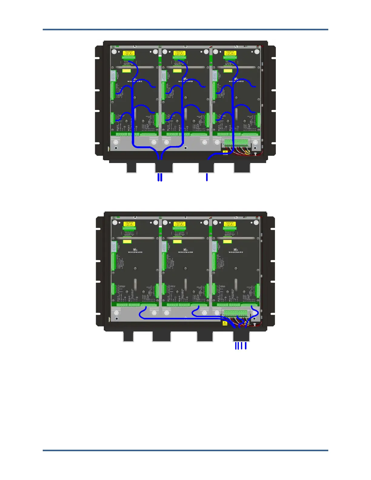
Figure 2-10b. I/O Wiring Routing & Stress Relief Diagram
Figure 2-10c. Relay Output Field Wiring Routing & Stress Relief Diagram
Speed Sensor Inputs
To sense speed, each ProTech-GII module (A, B, C) accepts a signal from a speed sensor mounted on a
gear connected to the turbine rotor or engine crankshaft. Speed sensors may be any of the following:
Passive magnetic pickup unit (MPU)
Active proximity probe
Eddy current probe
 Loading...