GENERAL
6 720 641 467 (2010/01)
11
5.10 APPLIANCE LAYOUT
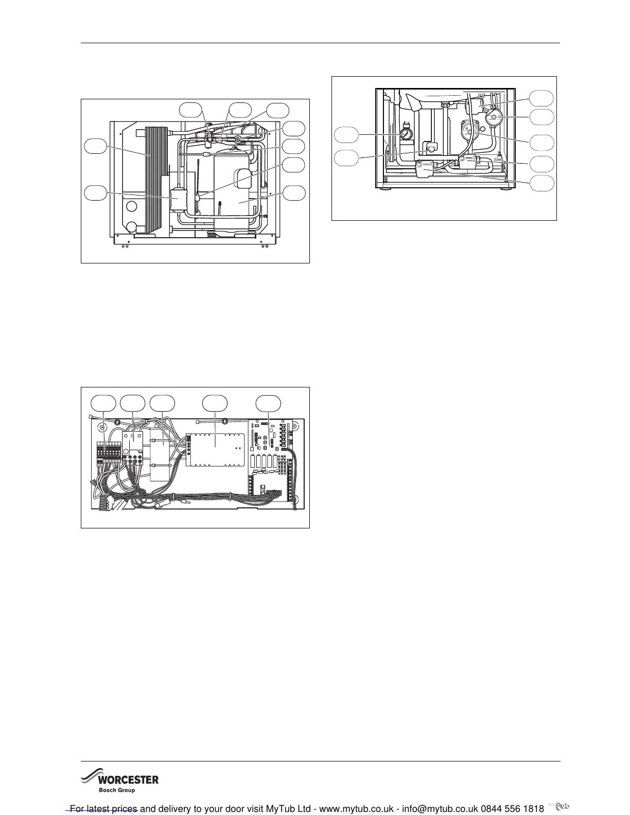
5.10.1 HEAT PUMP
Fig. 7 Greensource 6-9.5
1 Compressor
2 Dry filter
3 Heat exchanger
4 Sight glass
5 4-way valve
6 Low pressure switch
7 Expansion valve
8 Non-return valve
9 High pressure switch
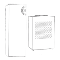
Fig. 8 Greensource 6-9.5 control panel
1 Terminal
2 Overload relay
3 Capacitor
4 Soft starter
5 PCB (IOB board)
5.10.2 INTERNAL UNIT HWDU-151
Fig. 9 Connection chamber, internal unit
1 Pressure gauge (System operating pressure 0.5 – 1.5 bar)
2 Mixing valve
3 Heat carrier pump (G2)
4 Pump for heating system (G1)
5 Heating three-way valve
6 Hot water three-way valve
7 Drain point
6 720 616 818-08.1I
1
3
2
7
6
5
4
9
8
6 720 641 467-70.1I
1
2
3 4
5
3
4
1
6 720 641 935-05.1I
2
5
6
7