ALARM FUNCTIONS AND DISPLAYS
6 720 641 467 (2010/01)
41
14.9 ALARM WINDOW
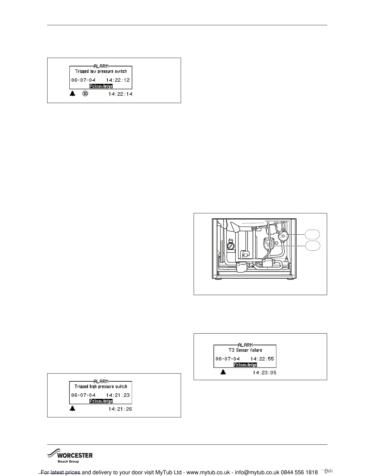
14.9.1 TRIPPED LOW PRESSURE SWITCH
Fig. 51
POSSIBLE CAUSE 1: EVAPORATOR BLOCKED.
B Clean the evaporator.
B Select Acknowledge.
B Wait until the heat pump starts again.
POSSIBLE CAUSE 2: FAN BLOCKED.
B Remove debris that blocks the fan.
B Select Acknowledge.
B Wait until the heat pump starts again.
POSSIBLE CAUSE 3: REFRIGERANT FAULT IN THE
REFRIGERANT CIRCUIT.
B Check the amount of refrigerant.
B Check the refrigerant circuit for tightness.
B Select Acknowledge.
B Wait until the heat pump starts again.
POSSIBLE CAUSE 4: FAULTY DEFROST SYSTEM OR
FAN MOTOR.
B Check the function of the 4-way valve. Manually
switch the 4-way valve in the corresponding menu
point at the control panel on and off.
B Check the defrost settings.
B Check the fan motor function.
B Select Acknowledge.
B Wait until the heat pump starts again.
POSSIBLE CAUSE 5: EXPANSION VALVE FAULTY.
B Check expansion valve.
B Check for overheating and excessive cooling.
B Select Acknowledge.
B Wait until the heat pump starts again.
14.9.2 TRIPPED HIGH PRESSURE SWITCH
Fig. 52
POSSIBLE CAUSE 1: AIR IN THE HEATING SYSTEM.
B Select Acknowledge.
B Check whether air is in the heating system.
B Fill the heating system and vent if required.
POSSIBLE CAUSE 2; BLOCKED PARTICLE FILTER:
B Select Acknowledge.
B Check filter.
B Clean filter if required (Æchapter 14.7).
POSSIBLE CAUSE 3: INADEQUATE FLOW RATE
ACROSS THE HEAT PUMP.
B Select Acknowledge.
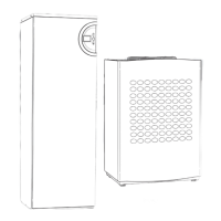
B Check whether the heat pump has stopped (Æ Fig. 53
on page 41).
B Check that all the valves are open. The thermostat
valves in heating systems should be fully open and in
floor heating systems at least half of the coils should
be fully open.
B Select a higher speed for the heat transfer medium
pump (G2). Also set a higher speed for the heating
circuit pump (G1), as it needs to run with a higher
speed than the heat transfer medium pump.
Fig. 53 Connection chamber, internal unit
1 Heating circuit pump, primary
2 Heating circuit pump, secondary
14.9.3 FAILURE / SHORT CIRCUIT ON SENSOR
Fig. 54
All sensors connected to the heating installation can give
an alarm in the event of a fault. In the example, it is
sensor T3, hot water, which has given an alarm. All
sensors give alarms in the same way.
6 720 641 467-18.1I
6 720 641 467-19.1I
1
2
6 720 641 935-08.1I
6 720 641 467-20.1I