ALARM FUNCTIONS AND DISPLAYS
6 720 641 467 (2010/01)
40
illuminate. Emergency mode can also be selected
manually. For this, activate the switch. The lamp inside
the switch extinguishes.
In emergencies heat generation is covered by the
electric additional heater. This enables heat to be
provided until the customer service remedies the fault.
14.6 OVERHEATING PROTECTION
A reset button is located inside the electric box of the
internal unit to reset the overheat protection of the
electric additional heater. Generally, this overheat
protection does not respond.
B Reset the overheat protection by pushing in the
button firmly.
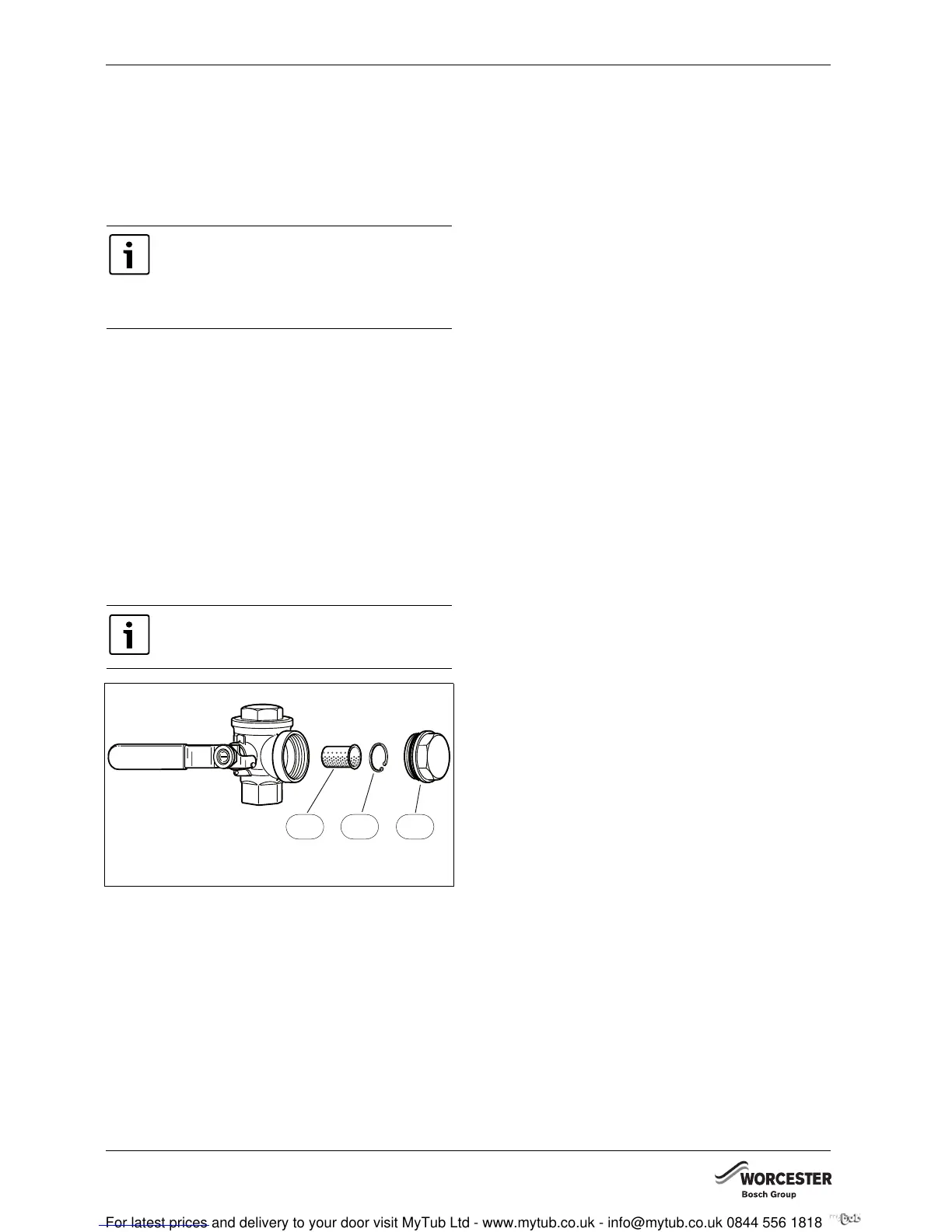
14.7 FILTER
The filter prevents particles and dirt from entering the
heat pump interior. Over time, the filter can become
blocked and must be cleaned.
Fig. 50
1 Filter
2 Locking ring
3 Plug
Cleaning the filter:
B Switch off the heat pump with the ON/OFF switch.
B Remove the valve and plug.
B Remove the locking ring that retains the filer inside
the valve. For this use the pliers supplied.
B Remove the filter from the valve and flush the filter
with water.
B Refit the filter, locking ring and plug.
B Open the valve and start the heat pump via the ON/
OFF switch.
14.8 ALL ALARMS AND WARNING
WINDOWS
An alarm can occur temporarily due to various reasons.
However, there is never a risk involved in resetting an
alarm. All the alarms that can appear in the menu display
are described in this section. The descriptions give an
idea about the nature of the alarm and what can be done
to rectify it.
The alarm log (see Advanced menu) shows the alarms
and warnings that have occurred.
14.8.1 LIST OF ALL ALARMS:
• Tripped low pressure switch
• Tripped high pressure switch
• Failure / Short circuit on sensor.
• Faulty function in 4-way valve
• T6 High hot gas temperature
• Fault on electric additional heat
• T8 High flow temperature.
• Low temperature in condenser
• Tripped motor cut-out
• Air/Water pump not connected
• Fault in I/O card control cabinet/electric boiler
• Tripped motor cut-out fan
14.8.2 LIST OF ALL WARNINGS:
• Is the heat pump fused for this output?
• High temperature difference heat transfer fluid
14.8.3 LIST OF ALL INFORMATION WINDOWS
• Heat pump is now working at its highest permitted
temperature
• Add. heat is now working at its highest permitted
temperature
• This setting means that additional heat can take
over operation
• Temporary stop of hot water production
• Temporary stop of compressor operation
Emergency mode must not be confused with
Alarm mode, which means that the heat
pump stops due to an active alarm. Heating
production is then still controlled by the
control unit.
Fit the filter into the heat pump return.
6 720 614 050-34.1D
1
2
3