HEATING SYSTEM CONNECTION
6 720 641 467 (2010/01)
16
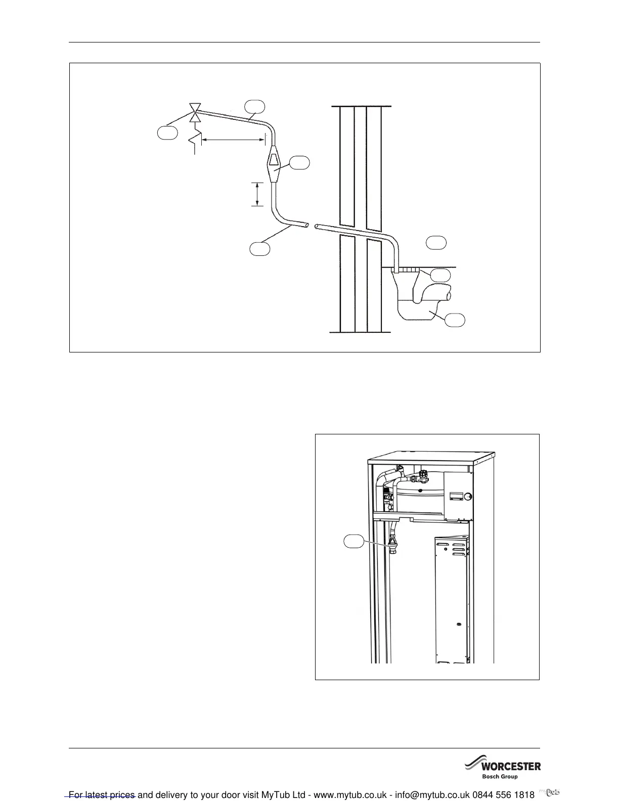
Fig. 15 Typical discharge pipe arrangement
1 Safety device (e. g. temperature pressure relief valve)
2 Metal discharge pipe (D1) from temperature relief value to
tundish
3 Tundish
4 Metal discharge pipe (D2) from tundish, with continuous
fall. See 3.9d i-iv, Table 1 and worked example.
5 Fixed grating
6 Trapped gulley
7 Discharge below fixed grating (3.9d gives alternative points
of discharge)
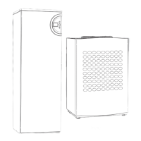
7.4 TUNDISH (HWDU)
Fit the tundish and straight fitting G1" x 28 mm as shown
on the illustration. The tundish and fitting are supplied
together with the HWDU as part of the G3 regulations.
Fig. 16
1 Tundish
6 720 641 467-75.1I
7
1
2
4
3
5
6
600 mm maximum
300 mm
maximum
6 720 641 467-76.1I
1