GENERAL
6 720 641 467 (2010/01)
8
5.6 CHECKLIST
5.6.1 GREENSOURCE 6-9.5 WITH INTERNAL UNIT
HWDU-151
1. Position the heat pump on a level and stable base.
2. Connect the flow and return pipes to the heat pump.
3. Fit the valve with filter.
4. Fit the drain pipe to the heat pump.
5. Fit the corresponding flow and return pipes to the
internal unit.
6. Connect the relief valve discharge pipe.
7. Connect the HWDU unit to the heating system or
buffer cylinder.
8. Fit the outside temperature sensor and, the room
temperature sensor.
9. Connect the CAN-BUS cable to the hwdu unit and the
heat pump.
10. Fill and vent the heating system.
11. Connect the power supply RCD and isolation
switches to both indoor and outdoor units.
12. Switch on the system. Make all required settings at
the control panel.
13. Check the heating installation after commissioning
and insulate all external pipe work.
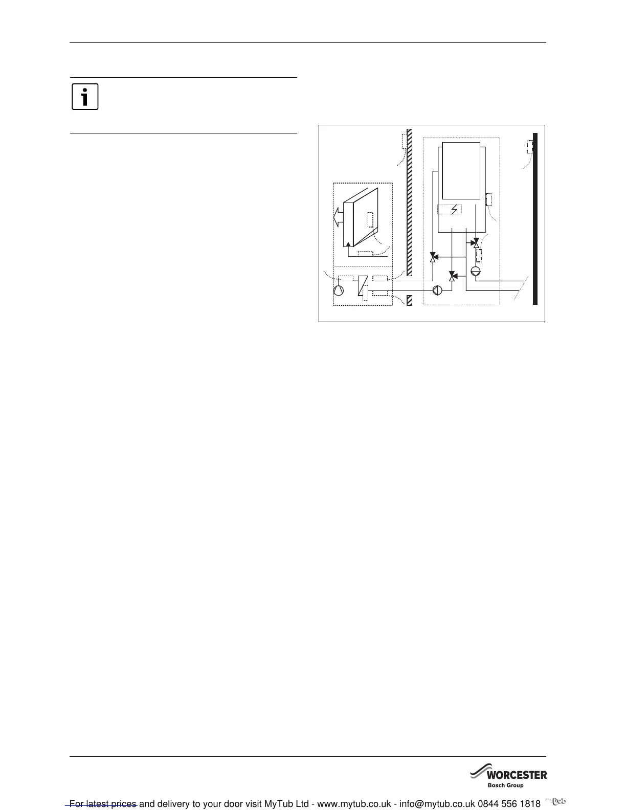
5.7 LOCATIONS OF THE TEMPERATURE
SENSORS
5.7.1 GREENSOURCE 6-9.5 WITH INTERNAL UNIT
HWDU-151
Fig. 3 Greensource 6-9.5 - internal unit HWDU-151
T1 Flow temperature sensor
T2 Outside temperature sensor
T3 Cylinder temperature sensor
T5 Room temperature sensor
T6 Hot gas temperature sensor
T8 Heating water temperature sensor, flow out
T9 Heating water temperature sensor, return in
T10 Condenser temperature sensor
T11 Refrigerant temperature sensor, evaporator
T12 Air temperature sensor, evaporator
Each heat pump installation is unique. The
following checklist will give you a general
description of how the installation should
be carried out.
6 720 616 817-03.1I
T5
T3
T1
T2
T9
T10
T8
T6
T11
T12