HEATING SYSTEM CONNECTION
6 720 641 467 (2010/01)
19
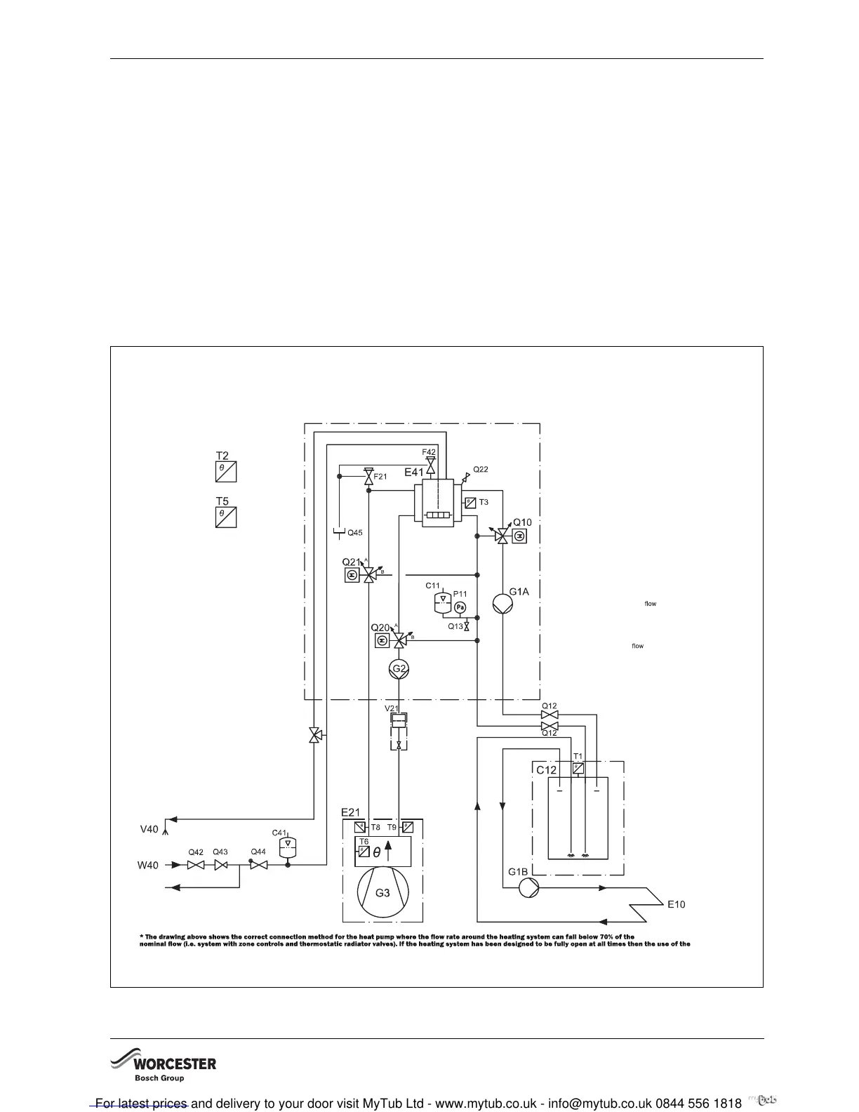
7.9 CONNECTION PRINCIPLE OF THE
INTERNAL UNIT
The principle method of operation is based on the
vapour compression cycle with any additional heat being
provided by the built in electric heater. The control unit
regulates the heat pump in accordance with the set
heating curve with the actual temperatures captured by
outside temperature sensor T2 and flow temperature
sensor T1.
When the heat pump can no longer meet the entire
heating demand on its own, the electric additional heat
in the internal unit starts and generates the temperature
required inside the building together with the heat
pump.
DHW heating has priority. DHW is regulated by means of
the actual temperature captured by cylinder
temperature sensor T3. Heating is switched off via the 3-
way valve when the DHW cylinder is being heated up.
The heating system will be supplied with heating water
again once the DHW cylinder has reached its set
temperature.
Operation in extreme cold conditions:
At an outside temperatures below approx. – 20 °C, the
heat pump stops automatically and can no longer heat
DHW. Under those conditions, the additional electric
heater in the internal unit automatically takes over the
DHW heating.
Fig. 19 Internal unit
Q46
E10 Radiator system
C11 Expansion vessel
C12 Primary water storage tank*
G1A Heating system pump
G1B ** Heating system pump
P11 Pressure gauge
Q10 Mixing valve
Q12 Isolating valve
Q13 Water outlet
E20 Heating system
E21 Heat pump
F21 Safety valve
G2 Heat carrier pump
G3 Fan
Q20 3-way valve
Q21 3-way valve
Q22 Air vent
V21 Filter heating system
E40 Tap water system
C41 Expansion vessel
E41 Hot water cylinder
V40 Hot water
W40 Cold water
F42 Temperature & pressure
relief valve
Q42 Isolation valve
Q43 Pressure reducing valve
Q44 Non return valve
Q45 Tundish
Q46 Blending valve
Sensors
T1 Heating system
sensor (indoor unit)
T2 Outdoor sensor
T3 DHW sensor
T5 Room sensor
T6 Hot gas sensor
T8 Heat pump
sensor
(outdoor unit)
T9 Heat pump return sensor
(indoor unit)
T10 Condenser
T11 Evaporator temp.
T12 Air intake
primary water storage tank is not required
** G1B is not supplied and should only be used in conjunction with the Primary water storage tank.
6 720 641 467-83.1I