POWER SUPPLY
6 720 641 467 (2010/01)
22
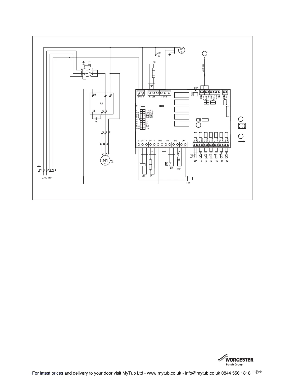
8.3 HEAT PUMP
Fig. 23 Greensource 6-9.5 wiring diagram
B1 Phase sequence relay
E3 Casing heater
E4 Optional heater cable
F1 Fuse
G3 Fan
K1 Compressor contactor
M1 Compressor
MB1 Compressor overload relay
Q4 4-way valve
R1 Soft starter
HP High pressure switch
LP Low pressure switch
S1 Termination switch
T6 Hot gas temperature sensor
T8 Heating water temperature sensor, out
T9 Heating water temperature sensor, in
T10 Condenser temperature sensor
T11 Refrigerant temperature sensor, evaporator
T12 Air temperature sensor, evaporator
1 Compressor type function jumper
2 Contact
3 Internal unit HWDU-151
1
2
6 720 641 467-73.1I
1
3