POWER SUPPLY
6 720 641 467 (2010/01)
23
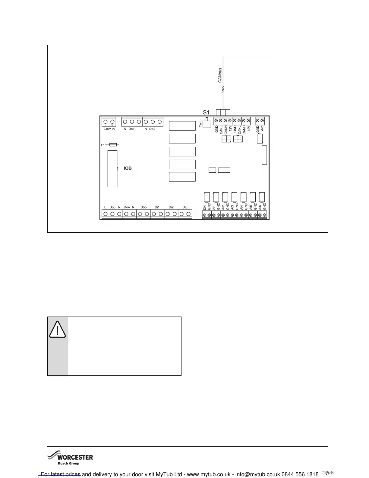
8.3.1 EXTERNAL HEAT PUMP CONNECTIONS
Fig. 24 External connections
POWER SUPPLY
Connect the power cable to terminals L1, N and PE
(Æ chapter 8.4). Ensure connection to the same phase
sequence as the internal unit.
CAN-BUS
Connect the screened communication cable between
the internal unit and the heat pump to terminals GND,
CANL, CANH and 12V (Æ chapter 5.8).
6 720 641 467-84.1I
CAUTION: Do not mix up the 12V and CAN-
BUS connections!
The processors are destroyed if 12V is
connected to the CAN-BUS.
B Check that the four cables are connected
to the contacts with the corresponding
marking on the circuit board.