POWER SUPPLY
6 720 641 467 (2010/01)
24
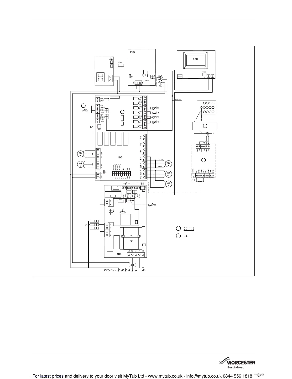
8.4 INTERNAL UNIT HWDU-151
8.4.1 WIRING DIAGRAM
Fig. 25 Wiring diagram
Do4 Open
Do5 Close
E1 Electric additional heater 4.5 kW
F1 Fuse
F21 Overheat protection
F31 Impressed current anode inside the DHW cylinder
G1 Heating circuit pump, secondary
G2 Heating circuit pump, primary
Q1 3-way valve
Q2 3-way valve
Q3 Mixer
S1 Termination switch
S2 Emergency switch
T Thermostat for emergency operation
T1 Flow temperature sensor, heating
T2 Outside temperature sensor
T3 Cylinder temperature sensor
T5 Room temperature sensor (accessory)
T99 Temperature sensor for emergency operation
1 Function jumper
2 Contact
3 Power guard (accessory)
4 Connect the power transformers to the incoming power
supply
5 Heating water outlet (towards the heat pump)
1
2
1
5
4
3
6 720 641 467-71.1I