POWER SUPPLY
6 720 641 467 (2010/01)
25
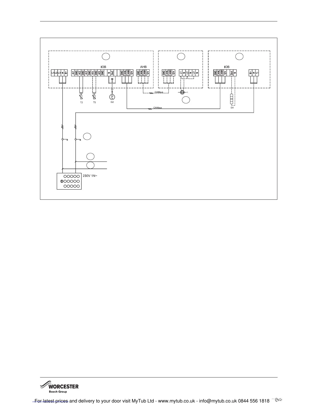
8.4.2 CONNECTION AT THE HEAT PUMP
Fig. 26 Connection diagram, heat pump - HWDU-151
E4 Heater cable (accessory)
G2 Primary heating circuit pump, not connected in the
delivered condition
T2 Outside temperature sensor
T5 Room temperature sensor (accessory)
1 Internal unit
2 Power guard (accessory)
3 Heat pump
4 Transformer for the voltage supplied by the large control
panel
5 Safety switch
6 Fuse:
Greensource 6: 16A
Greensource 7: 25A
Greensource 9.5: 25A
7 Fuse: HWDU-151: 25A
1
6 720 641 467-78.1I
2
3
4
5
6
7