INSTALLATION
6 720 806 548 (2013/02) 25
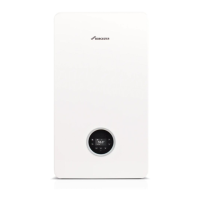
Fig. 37 Control panel access
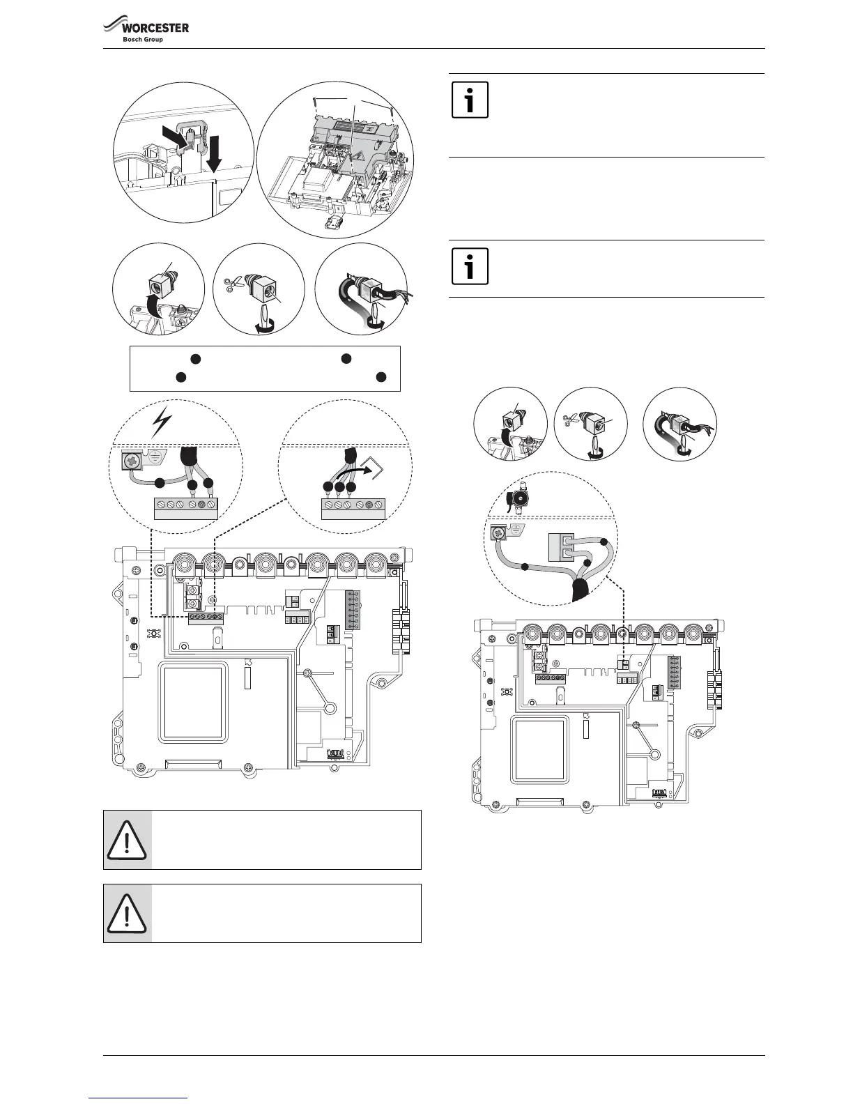
8. External Pump (ST2):
▶ Connect NEUTRAL wire to terminal (Nz)
▶Connect LIVE wire to terminal (Lz)
▶ Connect EARTH wire to earth bracket (E)
9. Refit control panel cover:
▶ Refit panel and secure with screws (B).
▶ Bring the control panel to its upper position and secure by sliding the
white plastic clip up.
Fig. 38 Electrical connections
CAUTION: Isolate the mains gas supply before starting
any work and observe all relevant safety precautions.
CAUTION: Short circuit
▶ When connecting the cables ensure that no cable
strands fall into the Heatronic.
The mains supply to the boiler must be fed through a
fused double pole isolator situated adjacent to the
appliance.
The isolator must have a contact separation of 3 mm
minimum in all poles.
The system pump must be connected to the appliance
control for the pump over-run facility.
 Loading...