COMMISSIONING
6 720 806 548 (2013/02) 29
5.6.1 CHECKING THE GAS INLET PRESSURE
The inlet pressure to the appliance must be checked using the following
procedure:
MEASURING THE INLET PRESSURE
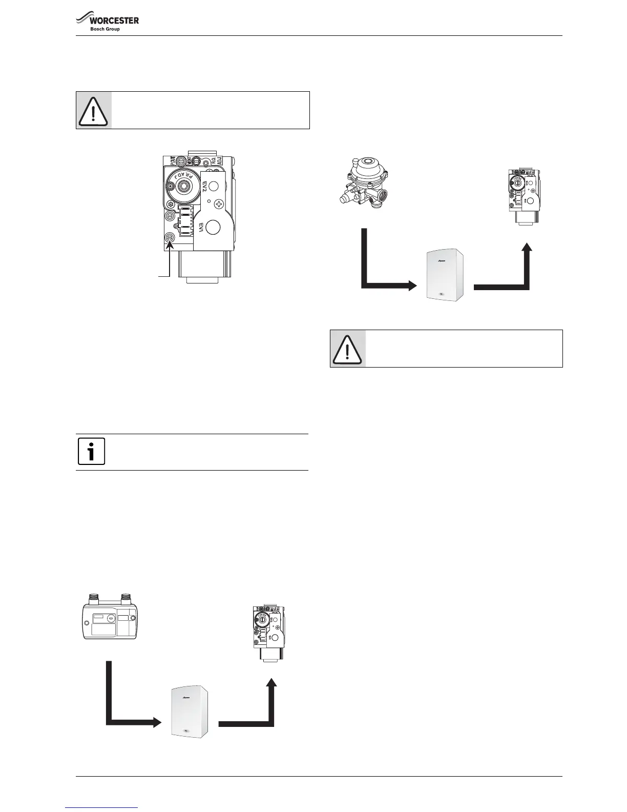
Fig. 43 Inlet pressure test point
▶ Close gas isolation valve.
▶ Slacken the screw in the inlet pressure test point and connect a
manometer.
▶ Open gas isolation valve.
▶ Measure the pressure with the boiler running at maximum.
– Press performance test button (L) for more than ten seconds and
set Central Heating temperature to maximum.
– The performance test button (L) will illuminate continually and the
blue power indicator will pulse five times.
▶ Check the gas supply working pressure at the gas valve conforms to
values shown in figures 44 or 45.
GAS PRESSURE WITHIN THE SYSTEM
Refer to the figure below for Natural Gas pressures.
The pressure at the boiler must not be less than the pressure read at the
meter minus 1 mbar.
The pressure drop from the meter to the gas valve must not be more than
2.5 mbar for natural gas.
If the pressure drops are greater than shown in the figure below, then
this would indicate a problem with the pipe work or connections within
the system.
Fig. 44 Natural gas pressures
Refer to the figure below for L.P.G gas pressures.
The pressure at the boiler must not be less than the pressure read at the
meter minus 2.5 mbar.
The pressure drop from the meter to the gas valve must not be more than
4mbar for LPG.
If the pressure drops are greater than shown in the figure below, then
this would indicate a problem with the pipe work or connections within
the system.
Fig. 45 L.P.G. pressures
▶ If pressure is satisfactory press the performance test button (L) again
and the boiler will return to normal operation.
▶ If left in the performance test mode the control will return to normal
operation after 15 minutes.
▶ Re-seal the screw in the gas inlet pressure test point.
5.6.2 CHECKING THE GAS RATE
▶ The gas rate should be measured at the gas meter after 10 minutes
operation at maximum.
See technical data section at the front of this manual.
▶ Where a gas meter is not available (e.g. L.P.G.) the CO/CO
2
must be
checked to the units shown in the setting of the air/gas ratio, refer to
section 6.2.
▶ If pressure and gas rate are satisfactory press the performance test
button again and the boiler will return to normal operation.
– If left in the performance test mode the control will return to normal
operation after 15 minutes.
▶ Close the gas isolation valve.
▶ Remove the manometer.
▶ Re-seal the screw in the gas inlet pressure test point.
▶ Open the gas isolation valve.
▶ Ensure that there are no gas leaks.
▶ Replace the outer case.
5.7 FINISHING COMMISSIONING
The boiler has been factory set, so there should be no need to adjust
combustion settings.
REPLACE OUTER CASING:
1. Replace outer casing making sure that the securing points are
properly located.
▶ Press the clip (A) downwards to secure casing on top.
▶ Retighten bottom two screws (B).
NOTICE: The combustion for the boiler is factory set.
No adjustment is required if the gas inlet pressure is
correct.
Ensure inlet pressure is satisfactory with all other gas
appliances working.