SERVICING AND SPARES
6 720 806 548 (2013/02)38
▶ Re-assemble with the new gasket and secure with the screws (F)
removed earlier.
Fig. 65 Electrode assembly
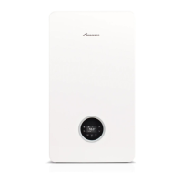
14. AIR/GAS MANIFOLD
1. Remove cover panel (A) by removing screws (B).
▶ Check that the boiler is completely isolated from the gas supply.
Fig. 66 Top panel
2. Remove clips (C) and unscrew the two bolts (D).
▶ Unscrew and remove the two hexagon screws (E) securing the fan.
▶ Slacken the rear securing bolt (F).
Fig. 67 Release air/gas manifold
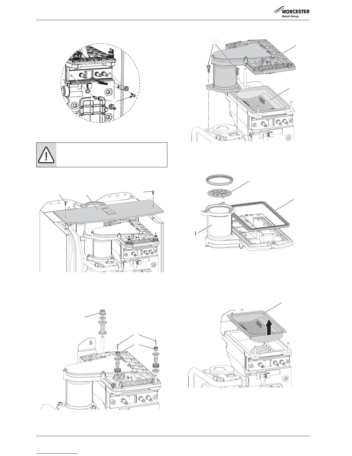
3. Remove air/gas manifold (I)
Fig. 68 Air/gas manifold
4. Open air/gas manifold (I).
▶ Carefully withdraw diaphragm (J) from fan intake tube and check for
soiling and splits.
Fig. 69 Diaphragm
15. BURNER
▶ Remove the burner (H).
▶ Replace new burner in correct position.
▶ Refer to section 6.1.5 “Re-assembly of the burner cover”
▶ Ensure that a new seal (K) is used, refer to fig. 69.
Fig. 70 Burner removal
16. HEAT EXCHANGER
▶ Isolate flow and return valves and drain the boiler.
▶ Remove condensate trap (see page 36).
▶ Remove fan assembly (see page 37).
WARNING: Air/Gas manifold
▶ Do not remove the manifold unless a new gasket is
available for re-assembly.
 Loading...