PRE-INSTALLATION
6 720 806 548 (2013/02) 9
S AND Y PLAN SYSTEM:
SYSTEM LAYOUT:
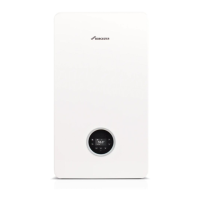
S PLAN LAYOUT
Fig. 5 S plan
Y PLAN LAYOUT
Fig. 6 Y plan
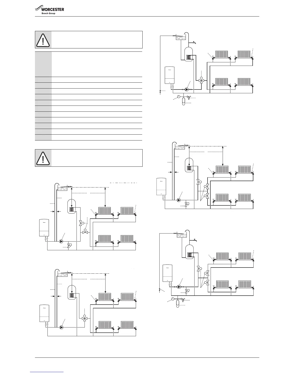
SEALED SYSTEM LAYOUT
Fig. 7 Sealed system
NEW BUILD SYSTEM LAYOUTS
The latest Part L1a regulation for new installations require separate zone
controls for the central heating.
Open vent with two heat zones
Fig. 8 Open vent with two heating zones
Sealed system with two heat zones
Fig. 9 Sealed system with two heating zones
NOTICE: Bypass
▶ Generally a bypass is not necessary on a Y plan system
as one of the ports is open to flow.
1 Static head -
Minimum static head 250mm measured from the highest
point in the heating system (top surface of the appliance or
the highest point in the heating system) to the water level in
the feed and expansion tank
2 Heating vent (22mm minimum)
3 Primary cold feed (15mm minimum)
4 Diverter/Zone valve
5 Pump, maximum power 90 Watts
6 Automatic bypass
7 Radiator valve (Flow)
8 Lock shield valve (Return)
9 Expansion vessel
10 Pressure gauge
11 3 bar pressure relief valve
12 Stop cock
Table 4 Key to figures 6, 7, 8 & 9
NOTICE: A drain cock should be fitted at the lowest
point of the heating circuit and beneath the appliance.