Commissioning
Greenstar Danesmoor Utility
ErP
and Utility System
ErP
- 6 720 813 286 (2014/09) 37
Fig. 62
▶ Repeat the procedure at least 3 times or until a steady stream of oil,
without air, runs from the bleed port, then lock the bleed port.
▶ Switch off the boiler.
▶ Remove the oil pump filter, clean with kerosene and refit.
The internal filter is accessed by removing the oil pump cover.
▶ Safely dispose of the container/discharge.
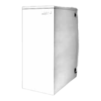
▶ Fit a suitable pressure gauge to port (A) on the oil pump.
▶ Adjust the air shutter (L) and pump pressure (B) as shown in the
table 8 on page 38. The burner should ignite following a pre-ignition
period of approximately 15 seconds.
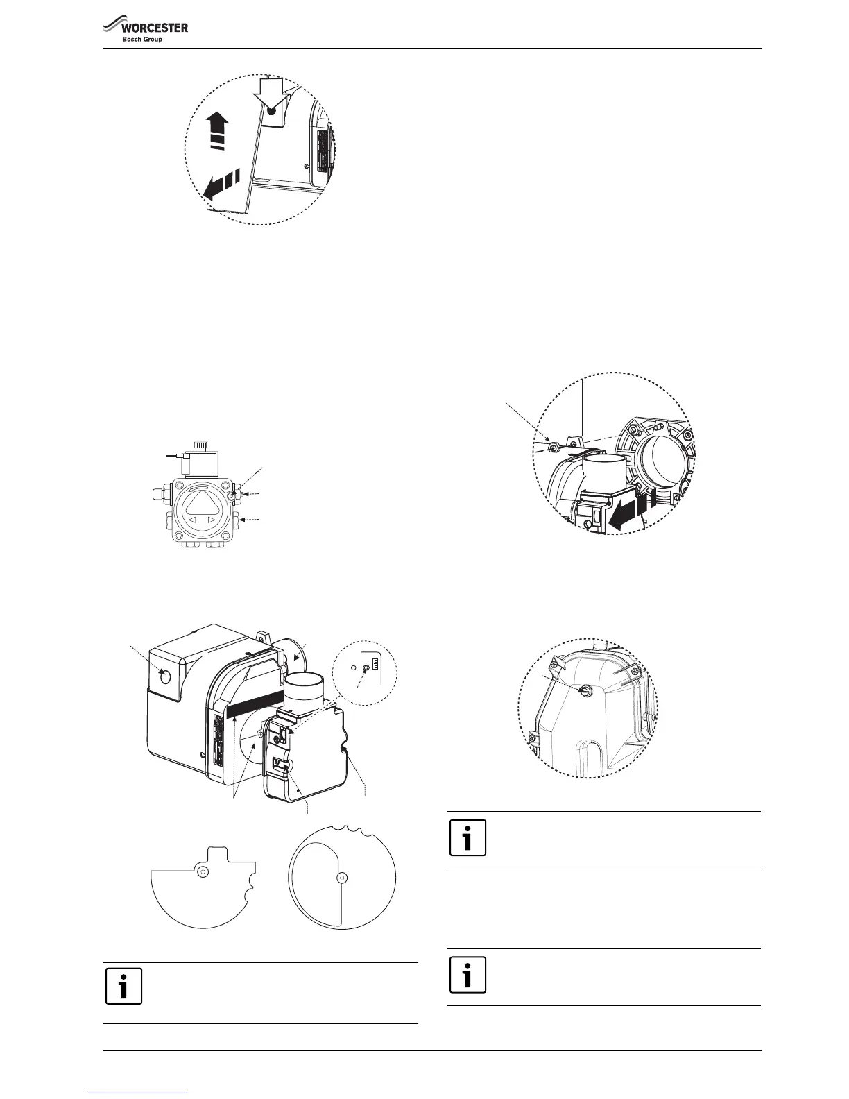
▶ If changing the burner output, check the position of the air damper
disc is correct to the output as shown in the table below.
Fig. 63
[A] Bleed and pressure gauge port
[B] Pressure adjustment
[C] Vacuum gauge port
Fig. 64
Boiler lock out indicator on:
If the burner fails to establish a normal firing pattern or flame failure
occurs the flame monitoring photocell mounted in the burner body will
alert the burner control box to shut the burner down and provide a safe
lockout state indicated by the illumination of the lockout indicator (D).
▶ Wait 2 minutes then press the lockout reset button D (see figure 67)
to initiate another start sequence.
▶ Repeat procedure until a flame is established.
1. Start and run for 3 minutes then switch off.
▶ Check for after-spurting from the nozzle, indicated by oil saturation
on the combustion head (G figure 67).
If after-spurting occurs:
▶ Release the burner retainer nut (F).
▶ Remove the burner, combustion head (G). and electrodes, hold the
burner vertical to unscrew the nozzle and fill the nozzle holder with
kerosene.
▶ Refit nozzle, electrodes, combustion head (G) and the burner.
▶ Restart and run for 3 minute intervals until after-spurting stops.
Fig. 65
2. Start and run for 20 minutes
▶ Remove sampling point plug (K) to check the smoke reading is
between 0-1. If the smoke level is above 1, check the combustion
settings are correct and the oil nozzle is in good condition.
Fig. 66
▶Check the CO
2
levels and adjust the air shutter (L) setting according
to the table opposite.
▶ Check the flue gas temperature is close to the values shown in the
table 8 on page 38.
Adjust position of air damper discs to suit burner output
(see table 8 on page 38), located as above. Access by
removing the two star screws (SC) to release the air inlet
manifold.
 Loading...