Commissioning
Greenstar Danesmoor Utility
ErP
and Utility System
ErP
- 6 720 813 286 (2014/09)38
▶ Turn off the electrical supply.
▶ Isolate the oil supply to the burner.
▶ Remove the oil pressure gauge.
▶ Refit the blanking plug (A).
▶ Check and rectify any oil leaks.
3. Switch on the oil supply.
▶ Switch on the electrical supply.
▶ Restart the boiler and run for 5 minutes.
▶Recheck the CO
2
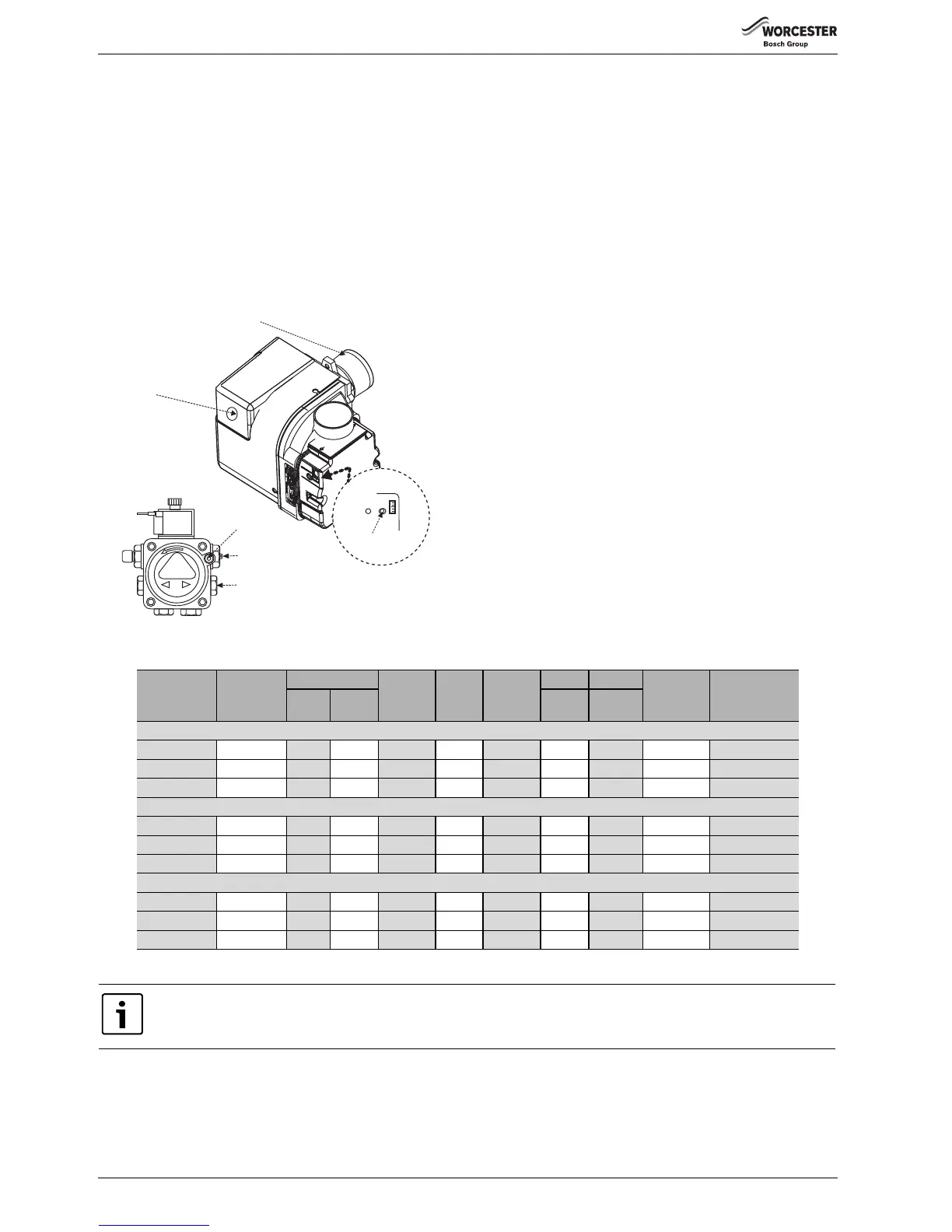
levels and if required, adjust the air shutter setting
(L) to obtain the correct CO
2
level.
▶ Refit the sample point cap (hand tighten only, do not over tighten)
and refit the burner cover.
Fig. 67
Nominal boiler rating at normal operating temperature using 28 second kerosene
Nozzle
Oil pump
pressure
(bar/psi)
Fuel flow rate Approx.
flue gas
temp. °C
%CO
2
Approx
air
setting
Input Output Air damper
disk
setting
Burner headkg/h l/h kW kW
Boiler 12/18 RDB 2.2
0.35x80°SR 9/132 1.04 1.32 72 11.0 3.0 12.3 12.0 12/15 LD2X Short
0.45x60°ES 7.5/110 1.28 1.63 77 11.5 5.0 15.4 15.0 12/15 LD2X Short
0.55x80°EH 7.8/115 1.54 1.96 80 12.0 5.0 18.5 18.0 18 LD2X Short
Boiler 18/25 RDB 2.2
0.50x80°ES 8.5/125 1.58 1.96 76 11.5 3.0 18.5 18.0 18 LD2SX Short
0.60x60°ES 8.5/125 1.84 2.33 81 12.0 3.5 22.1 21.5 21.5 LD2SX Short
0.75x80°ES 7.5/110 2.15 2.72 87 12.0 4.5 25.7 25.0 25 LD2SX Short
Boiler 25/32 RDB 2.2
0.75x80°ES 7.5/110 2.15 2.72 79 11.5 3.5 25.7 25.0 N/A T2 Short
0.75x80°ES 10/147 2.45 3.11 81 12.0 4.5 29.4 28.5 N/A T2 Short
0.85x80°EH 9.5/140 2.75 3.48 86 12.5 5.0 33.0 32.0 N/A T2 Short
Table 8 Burner information
APPLIANCE MUST BE SET TO CO
2
LEVELS.
AIR SETTINGS GIVEN ARE APPROXIMATE ONLY, AS FLUE LENGTH AND NOZZLE VARIATIONS WILL AFFECT THIS.
 Loading...