Service and Spares
Greenstar Danesmoor Utility
ErP
and Utility System
ErP
- 6 720 813 286 (2014/09)42
Service requirements
See the following instructions for detail of some of the service
requirements listed below:
▶ Check and clean the burner.
▶ Replace the burner nozzle and flexible oil pipe/s.
▶ Check and clean the baffle retainers.
▶ Check and clean the baffles.
▶ Check and clean the heat exchangers surfaces.
▶ Check the combustion chamber access door insulation board.
▶ Check that the flue system is unobstructed and clean as necessary.
▶ Clean or replace all oil filters.
▶ Check that the condensate system is not obstructed, clean and refill
the condensate trap.
Sealed system only
The PRV is a safety device and must be checked for correct operation.
The expansion vessel pressure must also be checked and adjusted if
required.
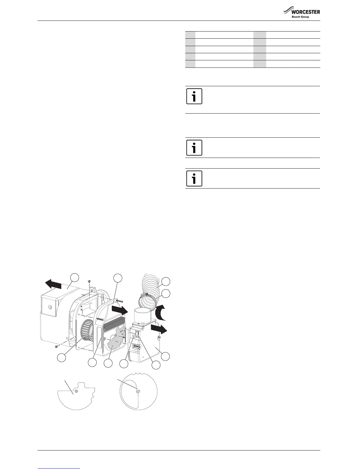
Clean the burner
▶ Remove plastic cover [1] from the burner.
▶ Unscrew to loosen the retaining ring [4]that secures the flexible air
supply tube [3] to the burner and remove from the burner.
▶ Loosen the 2 hex head screws and remove the air intake cover [5]
and clear any debris from the air intake and air damper [2],
(including the air damper disc [8], 12/18 & 18/25kW only).
▶ Check the condition of the black foam strip (12/18) [9].
▶ Note the position of the air damper adjustment [6] and check the air
damper [7] moves freely.
▶ Loosen the 4 hex head screws to disassemble the burner [2] to allow
access to the fan impeller [10].
▶ Check the condition of the gaskets between these parts and replace
is necessary.
▶ Clean both sides of the fan impeller and remove any debris from the
burner housing.
▶ Check the impeller [10] moves freely.
▶ Reassemble the components.
Fig. 76 Disassemble burner for cleaning
Refer to figure 77
▶ Remove the combustion head (B) and thoroughly clean any deposits.
▶ Remove the nozzle (C).
▶ Check the nozzle holder is clear of any debris and clean if necessary.
▶ Fit a new oil atomising nozzle (C).
▶ Check the electrodes (E) and reset if necessary as shown opposite.
▶ Refit the combustion head (B). Check that the nozzle (C) is central in
the combustion head (B) and the head settings are as shown. Ensure
that the photocell is lined up with the sight hole.
▶ Withdraw the photocell (F) from its housing and wipe clean.
▶ Remove the oil pump internal filter, clean in kerosene and
reassemble.
1 Plastic cover 6 Air shutter scale
2Air damper 7 Air shutter adjuster
3Hose clamp 8 Air shutter disk
4 Flexible air supply hose 9 Black foam strip (12/18)
5 Air intake cover 10 Impeller
Before removing or fitting a nozzle (C), loosen screw (D)
and move the electrodes (E) forward.
After refitting check that the electrode gaps are correct,
as shown opposite.
DO NOT dismantle the nozzle and DO NOT clean the
nozzle tip.
The 12/18 model has a brass air deflection washer and
locating circlip behind the nozzle. These must be in place
for the correct operation of the burner.
 Loading...