INSTALLATION
INSTALLATION & SERVICING INSTRUCTIONS
24
STANDARD FLUE INSTALLATION
8 716 115 216b (09.2008)
STANDARD FLUE INSTALLATION
TOP
110mm
3
B
K
G
F
H
E
E
G
H
J
C
4
5
6
A
Clip
C
B
A
2
B
1
A
TOP
TOP
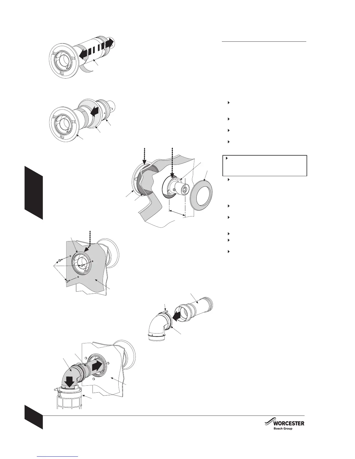
NOTE: To ease assembly of the flue components,
lightly grease seals lightly with the
solvent-free grease supplied.
Check all the seals are seated properly in
the grooves provided and are in good
condition.
All flue joints must be sealed to prevent
leakage of condensate and flue products.
Installing the standard flue:
1
Set the flue terminal (B) to the distance
required, secure with screw and seal joint
with the aluminium tape supplied.
2
Slide the inner wall seal (C) onto the
terminal (B) as shown.
If fitting from inside the building; slide
the outer wall seal (K) onto terminal (B).
3 Position terminal (B) through the flue
opening in the wall to the outside and then
pull back to create a seal.
The flue terminal (B) MUST be fitted
with the label marked 'TOP' uppermost
to allow the correct fit and use of the
plume management system.
If fitting from the outside of the building;
position terminal (B) through the flue
opening of the building by the distance
shown, slide the outer wall seal (K) onto
terminal (B) to fit against the outer wall.
4
Roll the boiler into position on the floor
mounting frame.
Position connector (A) with the label
marked ‘TOP’ uppermost to align with the
three holes in the boiler inner casing (E).
Secure using three hexagonal bolts (F).
5
Push-fit adaptor (G) into elbow (H) until
secured by the clip.
6
Slide adaptor (G) into the inner flue tube
of terminal (B) and push elbow (H) into
flue outlet (J) until secured by the retaining
clips ensuring a good seal is made.
 Loading...