ELECTRICAL
LN
L
R
L
S
N
S
ST10
LN
E
7
8
9
E L N
LZ
NZ
Switched live
Live
Neutral
Earth
230V
MAINS
SUPPLY
blue
brown
green/yellow
External
pump
Do not
remove link
(unless
used for
external
stat)
WIRING
SYSTEM
CENTRE
TIMER
ROOMSTAT
TANKSTAT
FROSTSTAT
WATER VALVE(S)
boiler
demand
ST25
ST8
ST10
External
stat
*
*
ST6
Condensate
pump
High level
sensor
B
B
4
2
1
F
A
ST19
ST6
ST8
ST25
ST19
LP
NP
FS
FR
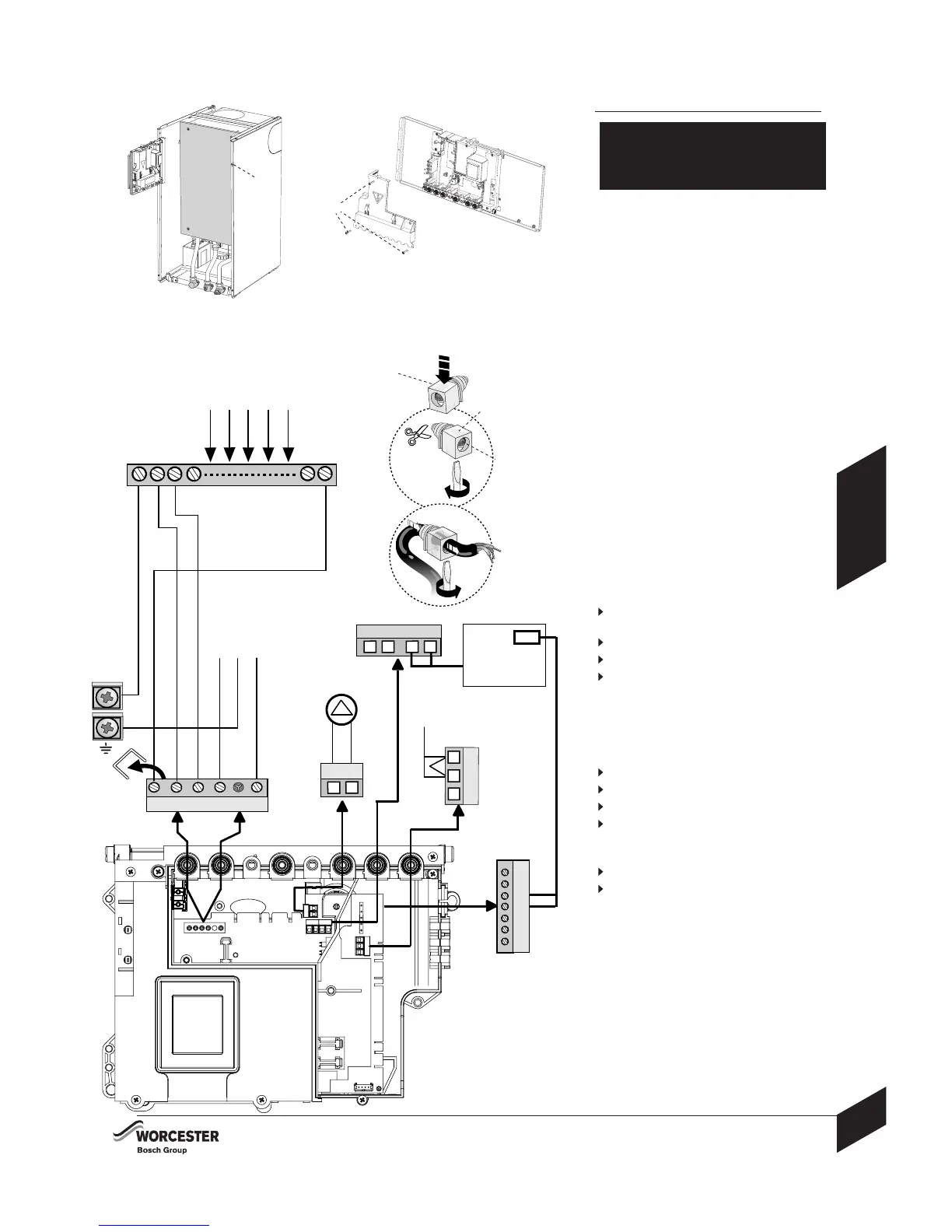
Note: Mains supply to the boiler and system
wiring centre must be through a common
fused double pole isolator situated next to
the boiler. The isolator must have a contact
separation of 3mm minimum between all
poles. Any system connected to the boiler
must not have a separate electrical supply.
External fuse 3 Amps.
When stripping wires ensure copper strands
do not fall into the control box.
Access to electrical connections:
Remove boiler casing to access control panel.
1 Remove screw (A) and swing the control
panel into the service position.
2 Remove the three screws (B) in the control
panel and remove the connections cover.
3 Unclip cable clamp (C).
4 Cut off the tapered cable entry to suit the
cable diameter.
5 Unscrew cable retaining screw (D).
Run the cable through the cable clamp (C)
ensuring there is ample cable to reach the
connectors.
6 Tighten the cable retaining screw D to secure
the cable and replace clamp C into the
control panel.
7 Mains power 230 Volt connection ST10:
Seperate wires from cable end and strip
to 6mm
Connect LIVE wire to terminal L
Connect NEUTRAL wire to terminal N
Connect EARTH wire to connector
NOTE:
Make the EARTH wire longer so that if the
cable is snagged, the EARTH wire is the last
to be pulled out.
8 System wiring centre connection ST10:
Remove link
Connect LIVE wire to terminal Ls
Connect NEUTRAL wire to terminal Ns
Connect SWITHED LIVE to terminal LR
9 External pump must be wired back to the
boiler:
Connect pump LIVE to terminal Lz
Connect pump NEUTRAL to terminal Nz
10 Refit all panels
NOTES:
External diverter valve(s) and all other 230V
parts are not supplied with the boiler.
Refer to manufacturers instructions when
connecting external parts to the wiring centre.
Worcester, Bosch Group cannot be held
responsible for wiring errors.
INSTALLATION
INSTALLATION & SERVICING INSTRUCTIONS
27
8 716 115 216a (07.2008)
ELECTRICAL
CAUTION: ISOLATE THE MAINS
ELECTRICITY SUPPLY BEFORE STARTING
ANY WORK AND OBSERVE ALL RELEVANT
SAFETY PRECAUTIONS
3
4
5
6
7
8
2
1
A
B
C
D
C
SYSTEM
WIRING
CENTRE
9
 Loading...