31
(b)
Remove the three remaining screws holding the front cover
plate in position and withdraw the cover to expose the fan
impeller.
(c) Clean both sides of the fan impeller and remove any debris
from the burner housing.
(d) Check that the impeller rotates freely.
(e) Clean the air inlet passage and check that the adjustment
mechanism, operates freely.
(f) Reassemble the components.
Electro Oil Inter B11 Burner
(a)
Remove the acoustic fan inlet cover.
(b) Remove the five screws holding the fan cowl in position and
remove the cowl noting how the fan control flap is positioned.
(c) Check that the air control flap pivots freely and ensure that
the air path to the burner head is clear.
(d) Clean both sides of the fan impeller and remove any debris
from the burner housing.
(e) Check that the impeller rotates freely.
(f) Reassemble the components.
Electro Oil Sterling Burner
(a)
Remove the air adjustment cover.
(b) Separate the main body of the burner from the burner front
by removing the M5 allen screw (located beneath the air
adjustment screw), using a 4mm allen key.
Check the condition of the gasket between these two parts and
replace if necessary.
(c) Note the position of the air damper adjustment and check the
air damper moves freely.
(d) Clean both sides of the fan impeller and remove any debris
from the burner housing.
(e) Check that the impeller rotates freely.
(f) Reassemble the components.
3. Remove the combustion head and thoroughly clean any
deposits.
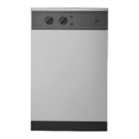
4. Inspection of Mechanical Shut-off Valve.
(a)
Remove the nozzle
(b) Fasten an M5 screw, with a minimum length of 30mm, into the
threaded hole (A) and pull the screw to withdraw the check valve.
(c) Check that the nozzle holder is clear of any debris and clean if
necessary.
(d) Check that the three holes in the check valve are clear of any
debris. Discard the check valve if the holes cannot be cleared or
if the unit is defective and replace with a new one.
(e) Replace in the reverse order.
5. It is strongly recommended that the oil atomising nozzle is
replaced at each service. If this is not possible then remove and
clean the integral filter. Under no circumstances should the
nozzle be stripped into its component parts and never attempt
to clean the nozzle tip.
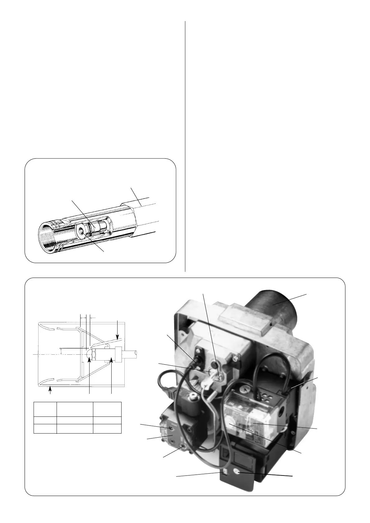
6. Check the electrodes and reset if necessary as shown in Figs.
23, 24, 25 and 26.
7. Replace the combustion head. Check that the nozzle lies
central to the combustion head and the head settings are as
shown in Figs. 23, 24, 25 and 26.
8. Withdraw the photocell from its housing and clean.
Check Valve
Nozzle Assembly
A
Fig. 22. Mechanical Shut-off Valve
Combustion head
Locking screw
Transformer
Photocell
Control box
Lockout reset button
Air adjustment screwAir control indicator
(4mm hexagonal head)
Oil pump
Pressure
adjustment
screw
Pressure gauge
port
Adjusting
disc
Dimension
Output Head Type A
12
PL 6/7/21.5/10-E 3 mm
14 PL 6/7/21.5/10-E 5 mm
To adjust the nozzle position,
undo the locking screw located
at the rear of the nozzle line and
rotate the adjusting disc one
turn anti-clockwise to move
forward by 1 mm.
Fig. 23. Electro Oil Inter B9A Burner.
(12/14 model).
Combustion Head
Draught tube
Nozzle Nozzle block
Spark gap
2-2.5 mm
2 mm
10 mm
A
 Loading...


