32
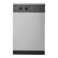
Combustion head
Locking screw
Transformer
Photocell
Control box
Lockout reset button
Air adjustment screw
Air control indicator
(4mm hexagonal head)
Oil pump
Pressure
adjustment
screw
Pressure gauge
port
Adjusting
disc
Dimension
Output Head Type A
15
PL 6/7/21.5/10 3 mm
16 PL 6/7/21.5/10 5 mm
17 PL 6/7/21.5/10 5 mm
To adjust the nozzle position,
undo the locking screw located
at the rear of the nozzle line and
rotate the adjusting disc one
turn anti-clockwise to move
forward by 1 mm.
Fig. 24. Electro Oil Inter B9B Burner.
(15/19 model).
Combustion Head
Draught tube
Nozzle Nozzle block
Spark gap
2-2.5 mm
2 mm
10 mm
A
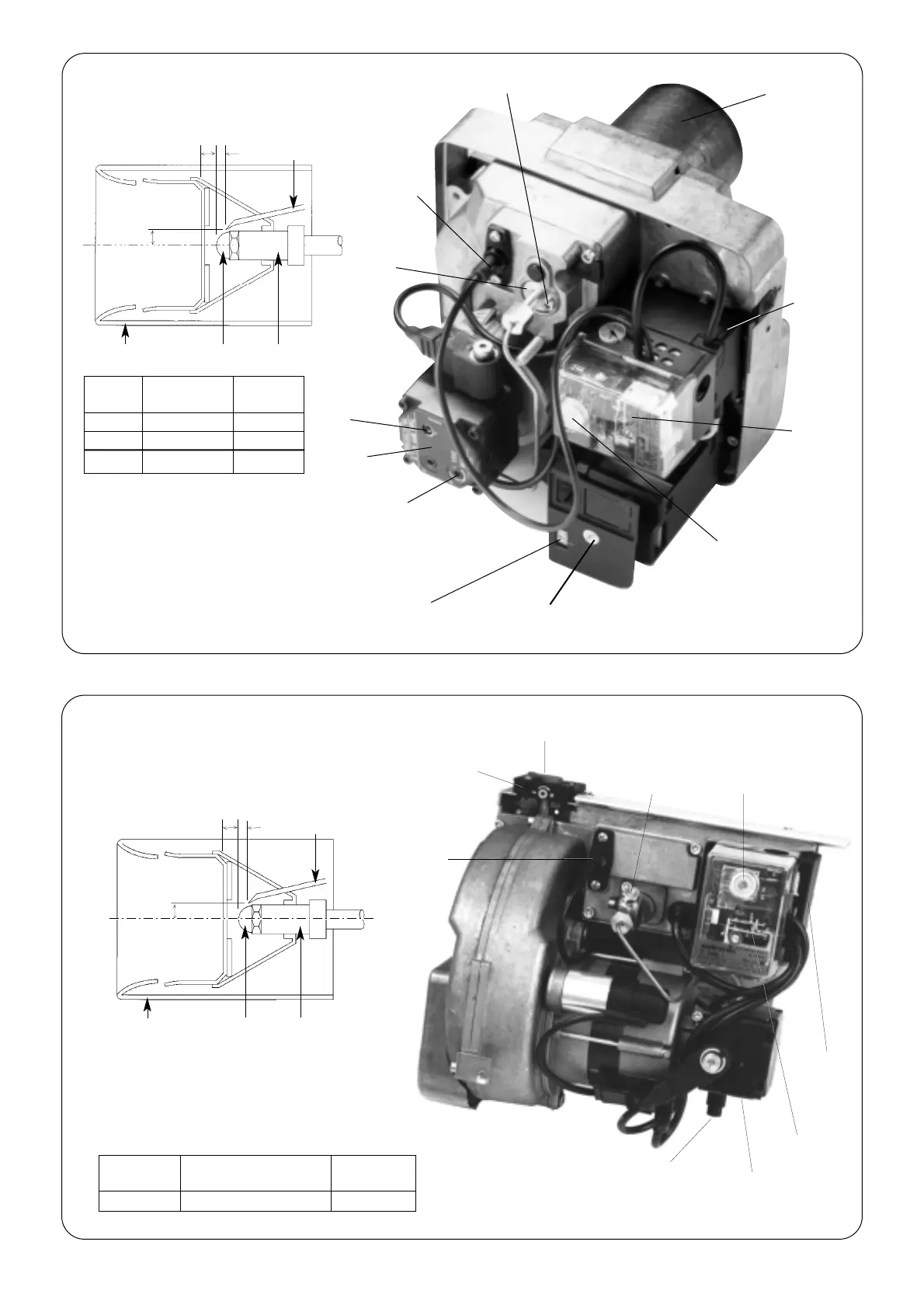
Fig. 25. Electro Oil Inter B11 Burner.
(20/25 model).
Combustion Head
Air control indicator
Photocell
Air adjustment screw
(4 mm hexagonal head)
Transformer
Control box
Oil pump
Pressure
adjustment
screw
Draught tube
Nozzle Nozzle block
Spark gap
3-3.5 mm
1 mm
8 mm
A
Lockout
reset button
Pressure
gauge port
Output
Combustion Head
Dimension
kW A
20/25 PL 10/4/24/10 x 78 mm 5 mm
 Loading...


