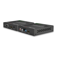
6
1312111098
7
654321
Rear Panel
# Name Description
1 20V Connect to the power adapter and the AC power cord provided.
2 USB-C Input 1-2
2 x USB-C ports that provide charging of the USB-C devices, 1000BASE-T Ethernet connection and dual-
video input (MST). Connect to USB-C sources.
3 HDMI Input 1-2 Connect to HDMI sources.
4 HDMI Output 1-2 Connect to HDMI displays.
5 Control Connect to network devices for LAN control, network access and Airplay Mirroring signal input.
6 Ethernet 1-2
For more information about the method of application for the three Ethernet ports, refer to the Network
Mode Conguration section.
7 USB 3.0 (1A) 1-3
3 x USB 3.0 type-A ports for the following two functions:
1. Connect to USB peripheral devices (e.g. keyboard, mouse, touch screen, camera, speakerphone, etc.) for
USB expansion. Note: Each USB-A port can output DC 5V 1A power to the attached USB peripheral
device.
2. Connect to a USB flash drive for rmware upgrade. More information, see Firmware Upgrade section.
8 USB HOST 1-2 2 x USB 3.0 Type-B connectors. Connect to USB host devices.
9 Mute Connect to the PA sensor for muting/unmuting the audio of HDMI OUT 1-2 and analog AUDIO OUT.
10 Relay Out Connect to a relay device for relay control.
11 RS-232
Serial port for the following two functions:
• Connect to the RS-232 port of an RS-232 device (e.g. a computer) to control this device.
• Connect to the RS-232 port of a peripheral (e.g. a projector) to control the peripheral.
Pins TX, RX, GND are used to control the attached RS-232 device.
Pins 12V, GND are used to output 12V DC power.
12 Audio Out 5-Pin analog audio port, connect to an audio receiver (e.g. an amplier) for audio de-embedded output.
13 Antenna Connect to the antenna set for the access to Miracast and soft AP function.
Installation and Wiring
Installation
Note: Before installation, please ensure the device is disconnected from the power source.
Attaching Antennas
1. Attach an antenna provided to the threaded connector, and screw it down clockwise.
2. Repeat the above step for other antennas.

 Loading...