Default Settings
8 Freedom XC PRO Owner's Guide
WARNING
ELECTRICAL SHOCK HAZARD
Use a torque screwdriver to tighten the captive nut panel screw to
5in-lb torque of force to ensure a proper ground connection and a
required tool access to the wiring compartment.
Failure to follow these instructions can result in death, serious
injury, or equipment damage.
Feature Description
1
Captive nut panel screw holds the AC compartment
cover in place. See WARNING above.
2 Ventilation grille (openings) must not be obstructed.
3
Grounding lug provides a ground path for the
Freedom XC PRO chassis to the DC system ground.
See WARNING.
4
DC terminal opening for routing (–) negative DC
cable.
5
DC terminal opening for routing (+) positive DC
cable.
6 LED indicator for reverse DC polarity.
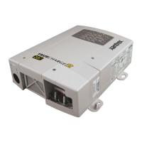
Table 2AC/DC and GFCI Panel Features
Feature Description
7
AC output terminal opening for routing AC output
wiring.
8
AC input terminal opening for routing AC input
wiring.
9
USB port can only be used for updating the unit’s
firmware. It is not used for powering USB devices.
10
LED indicator for communication and control
activation.
11
BTS port can be used for plugging in a battery
temperature sensor [BTS (PN: 808-0232-01), sold
separately].
12
Remote port allows you to connect the Freedom X
Remote Panel with cable (PN: 808-0817-01) (sold
separately) which is a remote control device
accessory.
13
20-pin CC (communications and control) port
connects with the optional 20-pin Communications
Harness (PN: 808-0820) (sold separately).
14
GFCI cover is removed when installing a qualified
GFCI device.
 Loading...