XCell
TM
ATF System with C410:V3 Controller
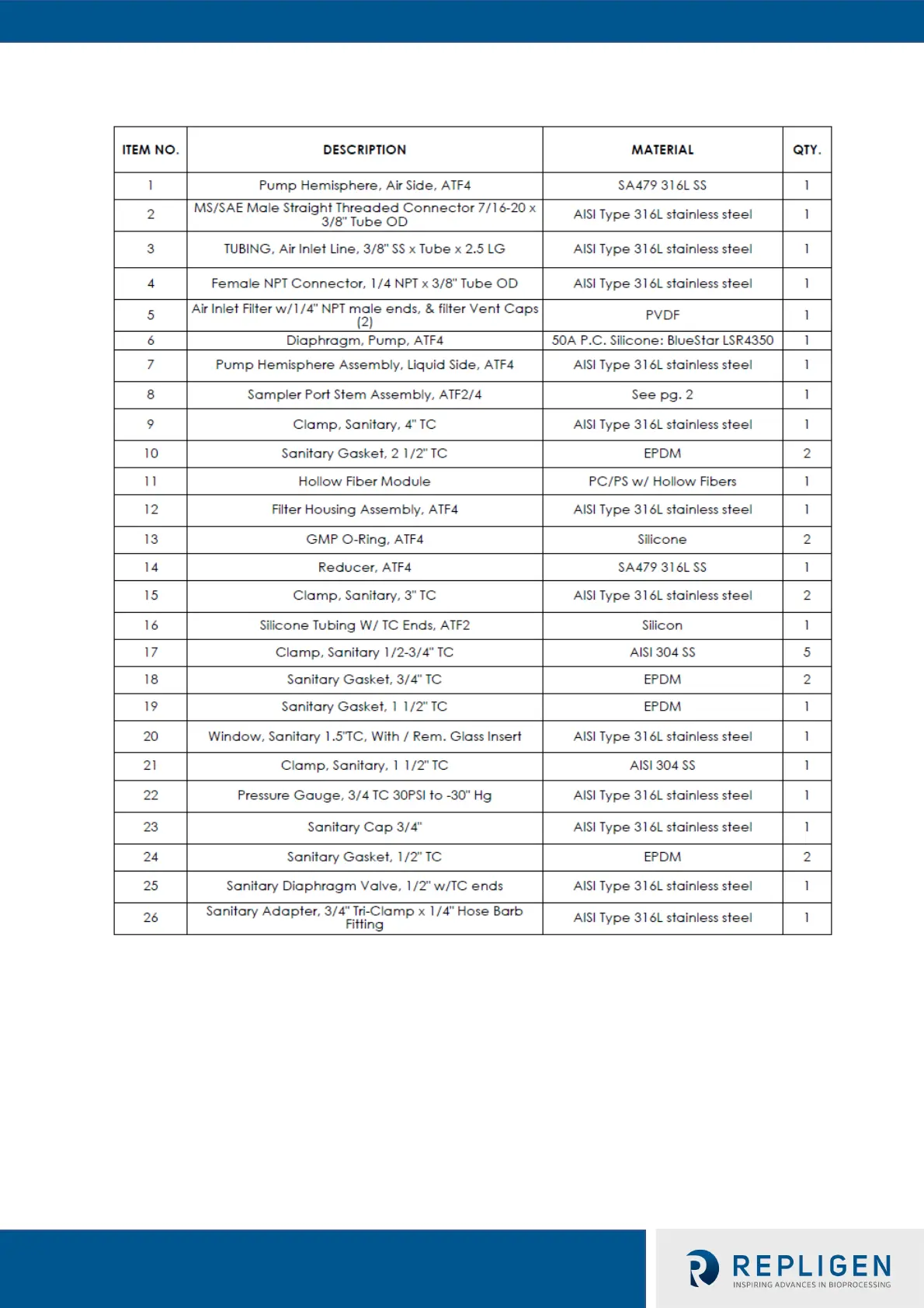
Table 4e. XCell™ ATF 4 Pump Housing Parts List
See Appendix 7 for list of spares and accessories
5. C410:V3 Controller Layout
5.1 General Layout
The controller consists of two parts: the E-Box, Figure 5, and the P-Box, Figure 4. The
two are interconnected with a cable that relays signal and power. A general layout of
the two boxes with the XCell
TM
ATF System is shown in Fig. 1. The primary design
objective is to produce a modular system that will maximize adaptability of the system
to the various space requirements of the user’s facilities. The Interconnect Cable, I-
Cable, connecting the E-Box and the P-Box can be selected to the required lengths to
 Loading...