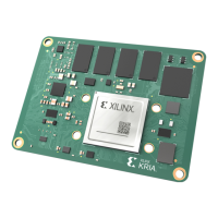
Figure 3: K26 SOM Samtec Connector Position Tolerance
Carrier Card Board to Board Connector
Placement Guideline
Corresponding to the Samtec 0.635 mm AcceleRate HD connectors (ADF6–60–03.5–L–4–2–A)
on the SOM, the mang connectors (ADM6–60–03.5–L–4–2–A) are placed on your carrier card.
The two SOM mang connectors must be placed and posioned using a ghtly controlled design
and manufacture processing. The following gure shows the keep-out area and connector
posion tolerance informaon used on an example carrier card design. The keep out area dened
maximum component height is 1.0 mm.
Chapter 3: Mechanical Design Considerations
UG1091 (v1.0) April 20, 2021 www.xilinx.com
Carrier Card Design for Kria SOM 41

 Loading...