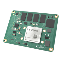
Figure 14: B2B Connector Orientation and Alignment
Board to Board Alignment Arrows
X25310-041621
Mating: JSOM Standoff-nut Tighten Sequence
and Torque Setup
To protect the mang connector from over mechanical stress and to minimize strain during
board-to-board assembly, it is important to ghten the stando nut in a specic sequence. The
recommended mechanical stando ghtening sequence (S > W > N > E) is shown in the
following gure. Once the S and W nuts are ghtened, the SOM board will be almost at to the
carrier card. The subsequent ghtening of nuts N and E ensure the SOM and carrier connectors
are completely engaged.
Chapter 3: Mechanical Design Considerations
UG1091 (v1.0) April 20, 2021 www.xilinx.com
Carrier Card Design for Kria SOM 52

 Loading...