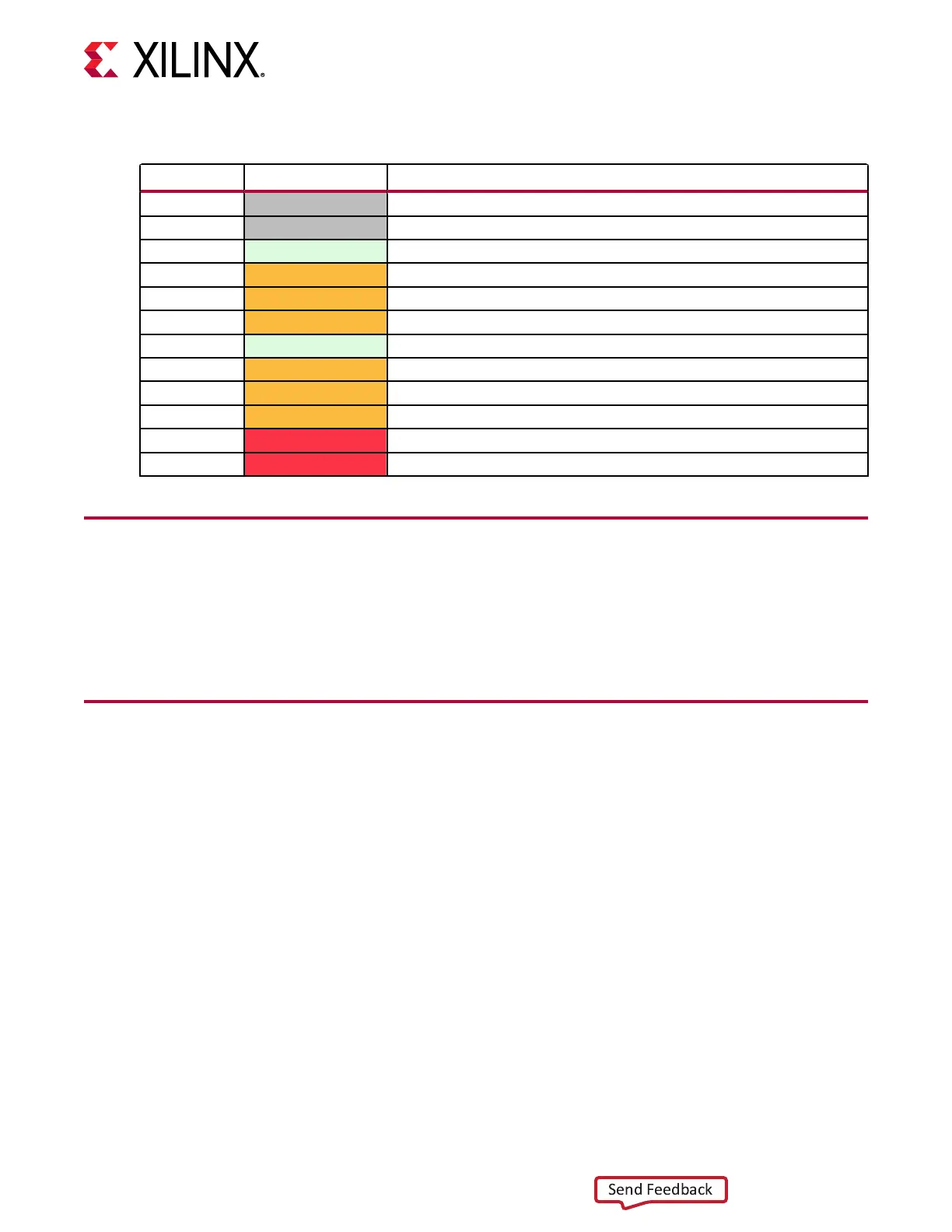
Table 6: SOM240_2 Signal Pins (cont'd)
Pin Number Signal Name Signal Description
D49 HDB04 HDIO on bank 43
D50 HDB05 HDIO on bank 43
D51 GND Ground
D52 HDC00_CC HDIO clock-capable pin on bank 44
D53 HDC01 HDIO on bank 44
D54 HDC02 HDIO on bank 44
D55 GND Ground
D56 HDC03 HDIO on bank 44
D57 HDC04 HDIO on bank 44
D58 HDC05 HDIO on bank 44
D59 VCCO_HDC HDC I/O voltage rail, 1.2V to 3.3V
D60 VCCO_HDC HDC I/O voltage rail, 1.2V to 3.3V
Supported I/O Standards
The K26 SOM supports all I/O standards supported by the respecve bank that a signal is
connected to with the excepon of I/O standards that require a reference voltage (V
REF
). For
more informaon, refer to the UltraScale Architecture SelectIO Resources User Guide (UG571).
Signal Routing Guidelines
This secon provides signal roung guidelines and required PCB layout constraints for all
interfaces provided on the SOM.
Note: Consult the UltraScale Architecture PCB Design User Guide (UG583) for detailed informaon.
MIO Signals
• Route all MIO signals MIO[77:26] as single-ended 50Ω traces.
• The maximum data rate supported on MIO signals is 250 Mb/s.
• Implement length matching as required by the interface used on individual MIO signal groups
dened by the applicaon MIO conguraon.
• All MIO signals must be 1.8V compable.
Chapter 2: Electrical Design Considerations
UG1091 (v1.0) April 20, 2021 www.xilinx.com
Carrier Card Design for Kria SOM 25

 Loading...