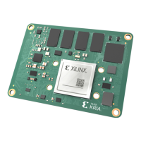
Figure 15: Connector Mating Sequence
SE
N W
The recommended torque driver seng and operaon parameters are specied in the following
table.
Table 18: Torque Driver Information
Torque Driver
Controller
Module
Torque Driver Torque Setting
Assembly
Duration
RPM Setting
for Each Step
Smart Torque
Electrical Driver
Atlas Copco
MTF600
ETD M 50 ABL V2 3.0 in.lbs
(±0.5 in.lbs)
10 secs Step 1: 300 RPM
Step 2: 600 RPM
Step 3: 150 RPM
De-mating: JSOM Standoff-nut and Jack Screw
Untighten Sequence
There is no special sequence required to unghten the four stando nuts. However, they must
be removed before proceeding to unghten the four jack screws. The order to unghten the four
jack screws is not crical. Once all four of the jack screws are completely unghtened, the SOM
board will pop up and the SOM connectors (male) automacally uncouple from the connectors
(female) on the carrier card. Remove the SOM by carefully holding the card on the two edges.
Chapter 3: Mechanical Design Considerations
UG1091 (v1.0) April 20, 2021 www.xilinx.com
Carrier Card Design for Kria SOM 53

 Loading...