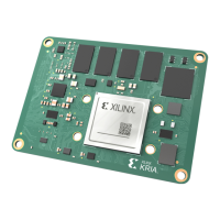
SOM System B2B Connector Assembly
Validation-DOE (To Ensure Time 0 No Crack)
The Samtec ADF and ADM connectors placement were shied 0% and 15% (based on connector
pad diameter) on the X and Y-axis for both the SOM and carrier cards. The shied connectors
were reowed and were able to mate without any issue.
The mated connector boards were submied for cross secon tesng to validate their mang
condions. Based on the cross-secon images, the connectors which shied by 15% were able
to self-align during reow soldering. The following photos are a cross secon image of the mated
connectors. The proper contact of the female and male connector pins is achieved.
Figure 16: Cross-section Image of Mated Connectors for 0% Shift
Figure 17: Cross-section Image of Mated Connectors for 15% Shift
Chapter 3: Mechanical Design Considerations
UG1091 (v1.0) April 20, 2021 www.xilinx.com
Carrier Card Design for Kria SOM 54

 Loading...