VC707 Evaluation Board www.xilinx.com 51
UG885 (v1.4) May 12, 2014
Feature Descriptions
User LEDs
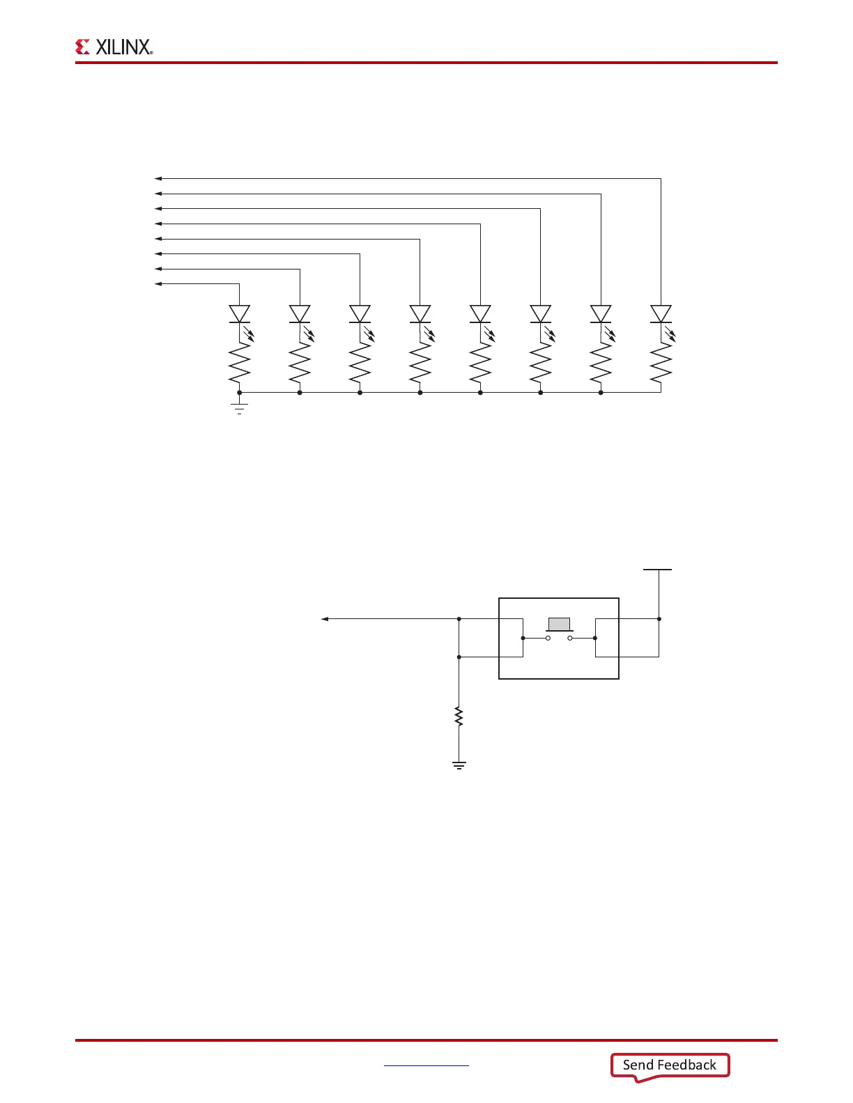
Figure 1-23 shows the user LED circuits.
CPU Reset Pushbutton
Figure 1-24 shows the CPU reset pushbutton switch circuit.
X-Ref Target - Figure 1-23
Figure 1-23: User LEDs
UG855_c1_23_020612
R147
49.9Ω
1%
DS2
R148
49.9Ω
1%
DS3
R149
49.9Ω
1%
DS4
R150
49.9Ω
1%
DS5
R151
49.9Ω
1%
DS6
R152
49.9Ω
1%
DS7
R153
49.9Ω
1%
DS8
R154
49.9Ω
1%
GND
DS9
GPIO_LED_6
GPIO_LED_4
GPIO_LED_5
GPIO_LED_2
GPIO_LED_0
GPIO_LED_1
GPIO_LED_3
GPIO_LED_7
X-Ref Target - Figure 1-24
Figure 1-24: CPU Reset Pushbutton
R41
4.7kΩ
0.1W
5%
GND
SW8
1
2
4
3
UG885_c1_123_012513
V
CC
1V8
CPU_RESET