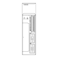
At the end of
instruction, the
absolute deviation
value under P5-00,
it outputs COIN
signal. If COIN
maintains P5-02
time, COIN-HOLD
signal is output.
|U0-08|
Pulse offset
P5-00
ON
/S-ON
Signal status
/COIN
Signal status
ONON
OFF
|ΔU0-12|
Pulse command
/COIN-HOLD
Signal status
ON
OFF
P5-02
P5-02
2. Description of positioning completion width
(1) The positioning completion width P5-00 changes proportionally due to the change of electronic gear ratio, and
the factory default is 11 command units.
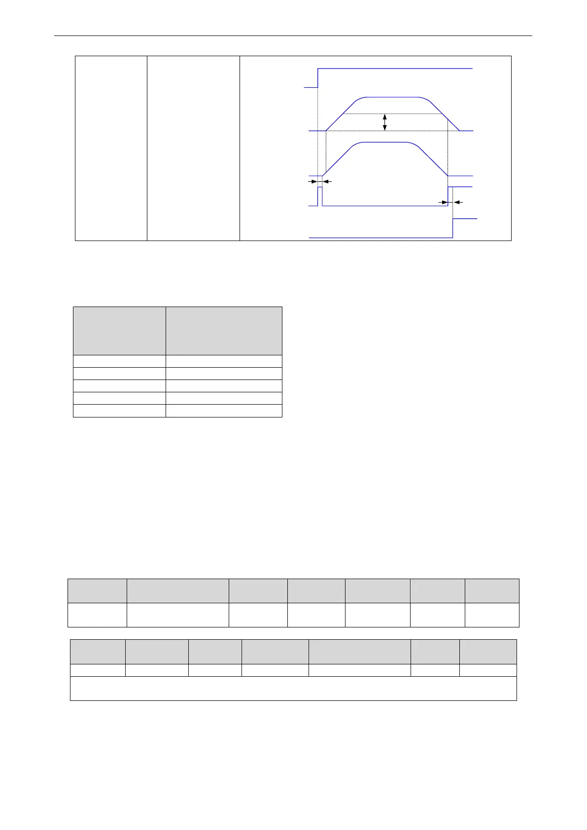
The following table is an example:
Number of
command pulses
required for one
revolution of motor
positioning completion
width P5-00
The positioning completion width P5-00 changes
proportionally with the number of command pulses
required for one revolution of the motor.
The output of the positioning completion signal
depends on the positioning completion width. The
smaller the width is, the later the positioning
completion signal output is, but the signal output
does not affect the actual operation state of the
motor.
(2) The positioning completion width can also be set separately, and its change will not affect the number of
command pulses required for one revolution of the motor.
4.3.1.3 Positioning near signal (/NEAR)
The servo motor is located near the positioning completion signal, so that the equipment can prepare the next
action in advance.
◼ Related parameters
Refer to section 3.2.2 for hardware wiring details.
If it is necessary to output from the SO2, P5-46 can be set to n.0002/0012.
1. Positioning approach signal output conditions
When the pulse deviation value U0-08 of the servo driver is lower than the P5-06 setting value, the positioning
approach signal (/NEAR) is output.
 Loading...