EasyManua.ls Logo

Xinje DF3E Series

Xinje DF3E Series
189 pages
To Next Page IconTo Next Page
To Previous Page IconTo Previous Page
Loading...
47
5. Segment number selection terminal logic is voltage level valid. Input high
voltage level is valid, input low voltage level is invalid.
The following input signal can switch the segment 1 to 3 or 1 to 8:
Parameter
Signal name
Default
setting
Suitabl
e mode
Setting range
Modify
Effective
P5-57
/PREFA internal
position segment 1
n.0000
5
Range 0000-0014, distribute
to input terminal through
P5-57
Anytime
At once
P5-58
/PREFB internal
position segment 2
n.0000
5
Range 0000-0014, distribute
to input terminal through
P5-58
P5-59
/PREFC internal
position segment 3
n.0000
5
Range 0000-0014, distribute
to input terminal through
P5-59
P5-60
/PREFD internal
position segment 3
n.0000
5
Range 0000-0014, distribute
to input terminal through
P5-60
3. Positioning mode
n.xxx□
Meaning
0
Relative positioning
1
Absolute positioning
0: relative positioning
1: absolute positioning
(take the reference origin as the absolute positioning
origin)
P
t
Segment 1
Segment 2
P
t
Segment 1
Segment 2
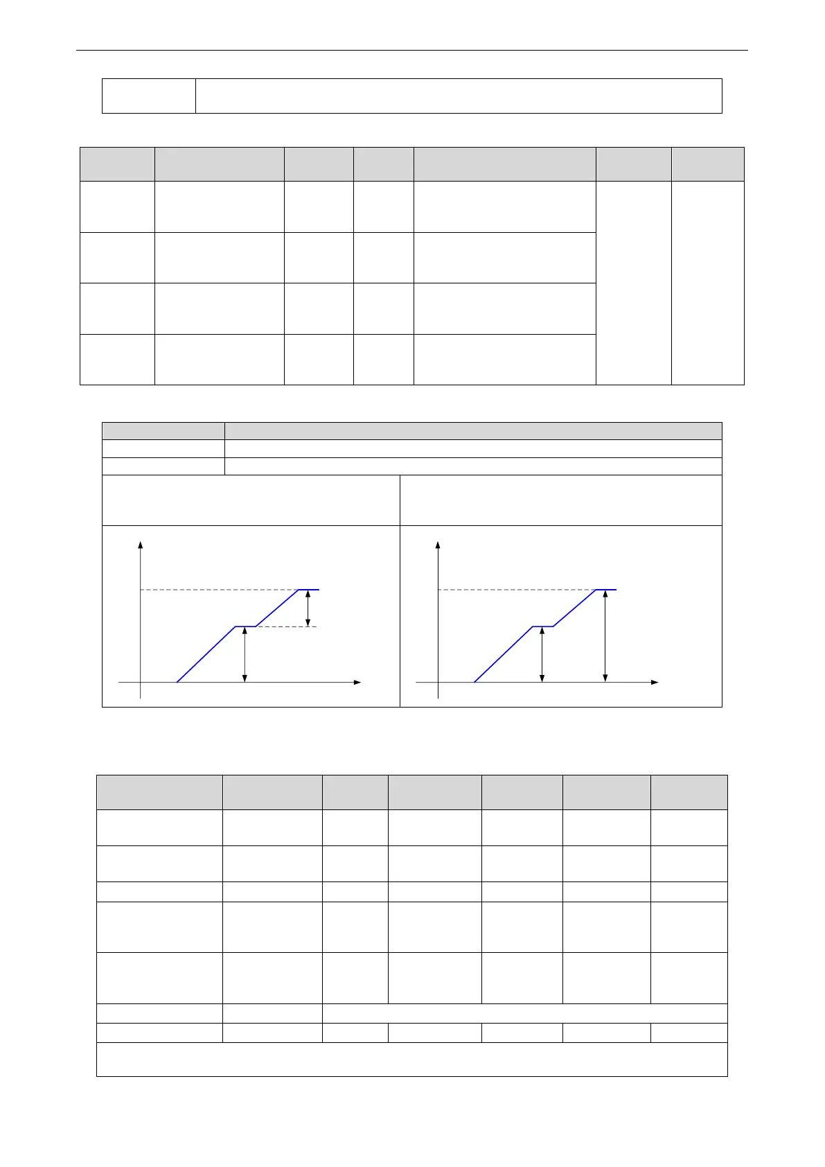
4.3.3.3 Position segment 1 to 35 parameter settings
Parameter
Meaning
Default
setting
Unit
Range
Change
Effective
P4-10+n-1*7
Pulse number
(low bit)
0
1 pulse
-9999
9999
Servo bb
At once
P4-11+n-1*7
Pulse number
(high bit)
0
10000 pulses
-32767
32767
Servo bb
At once
P4-12+n-1*7
Speed
0
0.1rpm
065535
Servo bb
At once
P4-13+n-1*7
Trapezoid
acceleration
time
0
ms
065535
Servo bb
At once
P4-14+n-1*7
Trapezoid
deceleration
time
0
ms
065535
Servo bb
At once
P4-15+n-1*7
Reserved
-
P4-16+n-1*7
Adjust time
0
ms
065535
Servo bb
At once
Notes:
1. Set pulse number = pulse number (high bit) ×10000 + pulse number (low bit).

Table of Contents

Related product manuals