r = reserved (No correspondence) w = warning
sod = switch on disabled
oms = operation mode specific qs = quick stop
(control mode based on bit) ve = voltage enabled
ila = internal limit active f = fault
oe = operation enabled
rm = remote so = switched on
rtso = ready to switch on
bit10 (target reached (Velocity reached)):
The difference between the total value of 60FFh (target velocity) and 60B1h (velocity offset) and 606Ch (velocity
actual value) is within the range set by 606Dh (velocity window). If the time set by 606Eh (velocity window time)
passes, bit10 of 6041h (status word) becomes 1.
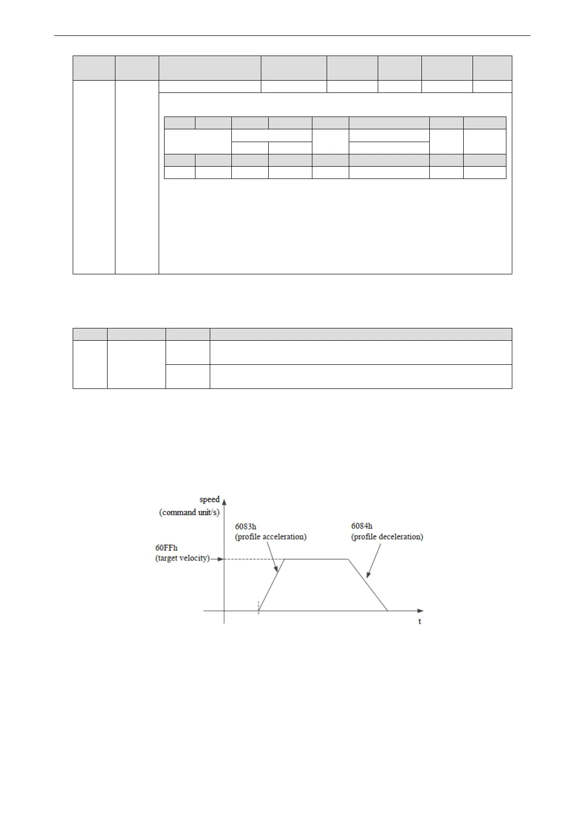
4. PV control mode action explanation
PV control mode generates speed command based on below parameters:
Target Velocity (60FFh) Profile acceleration (6083h)
Profile deceleration (6084h)
Turn off motor enable, set object word 6060h to 3, set target speed 60FFh, acceleration and deceleration 6083h
and 6084h, speed 6080h and torque limit 6072h. The target speed is 60FFh, the maximum speed is limited by
6080h (max motor speed), and the torque is limited by 6072h (max torque). Turn on the motor enable, the motor
should start to move according to the set value.
5. Operation example
Taking Xinje DF3E low-voltage servo as an example, the configuration and control process of PV mode are
briefly introduced. The specific use method of servo software is shown in Appendix 10.
① click [scan] or [add slave station] in CANopen configuration interface, configure the object binding of TxPDO
and RxPDO. Here, several common objects of PV mode are bound. If you have other requirements, you can add
them by yourself and enable the configured PDO. The specific configuration is shown in the figure below.
TxPDO (monitor parameters):
 Loading...

