V5 series inverter
62
P3.09.
Lowest bit of LED: Set baud rate, the values are shown below:
0: 1200BPS
1: 2400BPS
2: 4800BPS
3: 9600BPS
4: 19200BPS
5: 38400BPS
Ten bit of LED: Set digital format, the values are show below:
0: 1-7-2 format, no parity check; 1 stop bit, 7 data bits, 2 stop bits, no parity.
1: 1-7-1 format, odd; 1 stop bit, 7 data bits, 1 stop bits, odd
2: 1-7-1 format, even; 1 stop bit, 7 data bits, 1 stop bit, even
3: 1-8-2 format, no parity check; 1 stop bit, 8 data bits, 2 stop bits, no parity.
4: 1-8-1 format, odd;1 stop bit, 8 data bits, 1 stop bit, odd
5: 1-8-1 format, even;1 stop bit, 8 data bits, 1 stop bit, even
6: 1-8-1 format, no parity check; 1 stop bit, 8 data bits, 1 stop bit, no parity.
Hundred bit of LED: undefined
Note: when choose Modbus-RTU communication mode, you should select digital format 3~6.
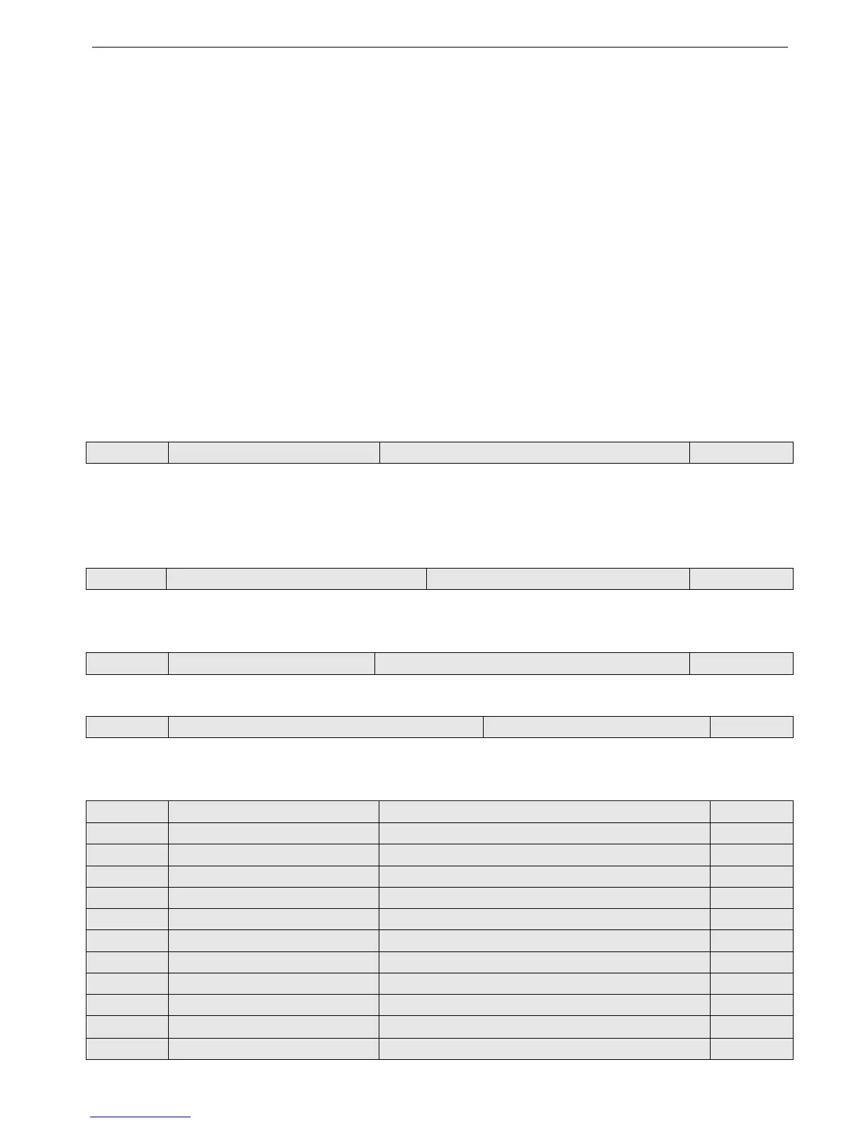
P3.10 Inverter address Range: 0~248 1
This parameter is used for identify the inverter’s address in serial communication.
0 is the broadcast address. If inverter is a slave, it doesn’t have to answer the 0 command.
248 is inverter host address. If set P3.10 to 248, it can send broadcast command to other inverters to realize multi-machine
working.
P3.11 Communicate overtime checking time Range: 0.0~1000.0S 0.0s
When serial port communication failed and the lasting time is over this parameter, the inverter is considered as communi-
cation error.
When set the value to 0, the inverter will not detect the serial communication port and this function is disabled.
P3.12 Inverter response delay Range: 0~1000ms 5ms
It refers to time from inverter’s serial port receiving and executing the command of host PC to returning response to it.
P3.13 Proportion of communication frequency Range: 0.01~1.00 1.00
The real running frequency= the proportion * frequency command receiving from RS485 port.
This parameter can also set running frequency proportion of several inverters in multimachine linkage mode.
P3.14 Accerlate time 2 Range: 0.1~6000.0 10.0
P3.15 Decelerate time 2 Range: 0.1~6000.0 10.0
P3.16 Accerlate time 3 Range: 0.1~6000.0 10.0
P3.17 Decelerate time 3 Range: 0.1~6000.0 10.0
P3.18 Accerlate time 4 Range: 0.1~6000.0 10.0
P3.19 Decelerate time 4 Range: 0.1~6000.0 10.0
P3.20 Accerlate time 5 Range: 0.1~6000.0 10.0
P3.21 Decelerate time 5 Range: 0.1~6000.0 10.0
P3.22 Accerlate time 6 Range: 0.1~6000.0 10.0
P3.23 Decelerate time 6 Range: 0.1~6000.0 10.0
P3.24 Accerlate time 7 Range: 0.1~6000.0 10.0
P3.25 Decelerate time 7 Range: 0.1~6000.0 10.0