Xtreme Power Conversion Corporaon
TX91 3.8- 10kVA User’s Manual
Page 11
Uninterrupble Power Supply
2. Connect input L2 wire to UPS input L2 terminal.
3. Connect input GND wire to input GND terminal.
4. Connect output L1 wire to UPS output L1 terminal.
5. Connect output L2 wire to UPS output L2 terminal.
6. Connect output N wire to UPS N terminal.
7. Ensure ISO TAP Jumper is in correct posion (208V for 208V input or 240V for any other input
voltages).
8. Ensure Output voltage parameter is set to match the site input voltage. Refer to secon 3.3
NOTE 1: The ISO Tap Selector Jumper is electrically located between the output of the inverter and the
transformer primary. In the 208V posion it steps up the voltage by 11%. In the 240v posion there is
no voltage change. 208V is default Posion. Refer to gure 2-4.
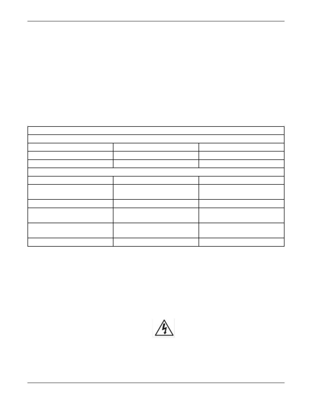
Voltage Conguraon Chart
Standard Sengs
Input Voltage Iso Tap Posion Voltage Out
208 208 230/115 (Default)
240 240 240/120
Addional Sengs
Input Voltage Iso Tap Posion Voltage Out
200 208
240
222/111
200/100
208 240 208/104
220 208
240
244/122
220/110
230 208
240
256/128
230/115
240 208 266/133
NOTE 1: If other than default seng is desired, conguraon can be done at the factory for an
addional voltage conguraon fee.
6. Aer connecng the wires, replace the terminal block cover on the rear panel of the UPS.
NOTE 1: Install the output breaker between the output terminal and the Load. I.A.W NEC code.
NOTE 2: UPS Cabinet contains an Isolaon Transformer with N-G bond. This system qualies as a
separately derived source.
Warning:
Make sure the UPS is turned o before installaon.
The UPS should not be turned on during wiring connecon.