Appendix C – Pinouts
C-3
Serial Port Connectors
There are two serial ports supported on the AHIP4+ and the AHIP5+ boards.
COM1
COM1 consists of two connectors attached to one logical port. Only one connector can
be used at a time either the RS-232 port or the RS-485 port. All termination is done out-
side the unit.
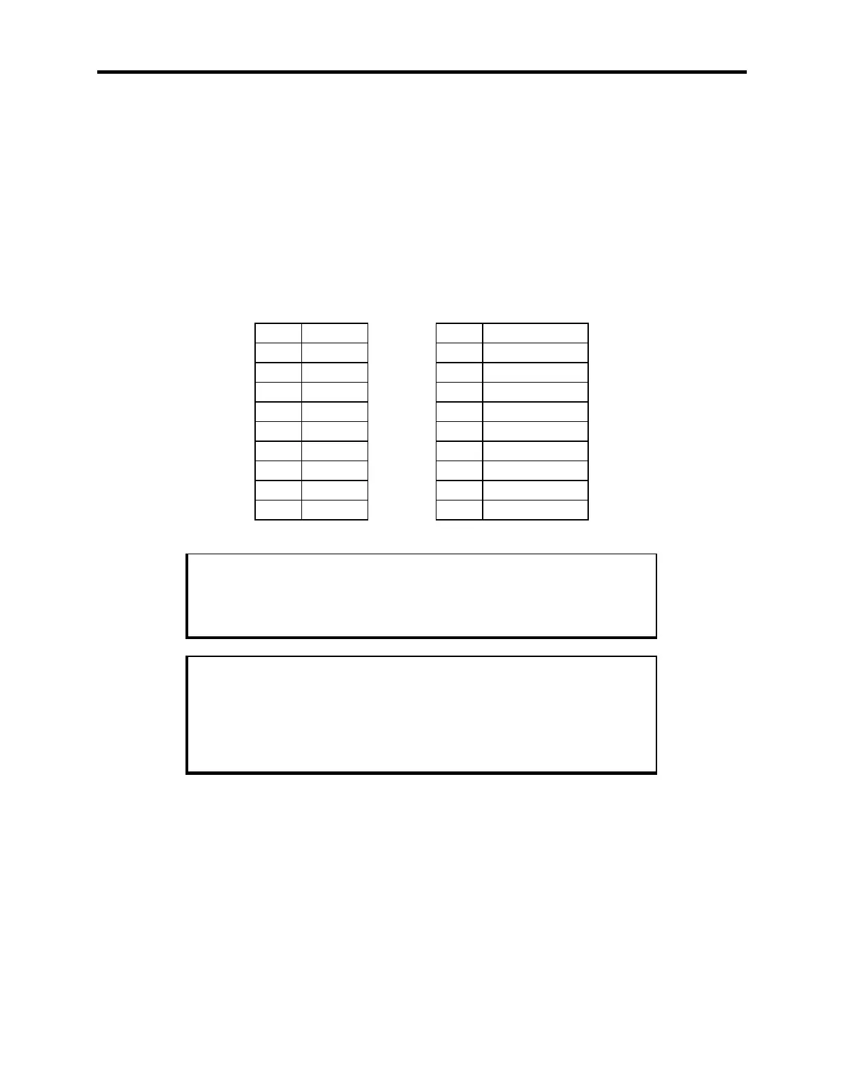
RS-232 RS-485
Pin Signal Pin Signal
1A DCD1 1B TXD-
2A RXD1 2B TXD+
3A TXD1 3B TXD TERM -
4A DTR1 4B TXD TERM +
5A GND 5B GND
6A DSR1 6B RXD-
7A RTS1 7B RXD+
8A CTS1 8B RXD TERM +
9A RI1 9B RXD TERM -
Note
“A” denotes the lower connector (RS-232) and “B” denotes the upper
connector (RS-485).
Note
For TXD termination, connect a 150Ω, ½ watt resistor from pin 3B to pin
4B, with pin 1B connected to pin 3B and pin 2B connected to pin 4B. For
RXD termination, connect a 150Ω, ½ watt resistor from pin 8B to pin 9B,
with pin 6B connected to pin 9B and pin 7B connected to pin 8B.