en - Original instructions
Genyo plus, Additional Installation, Operation and Maintenance Instructions 15
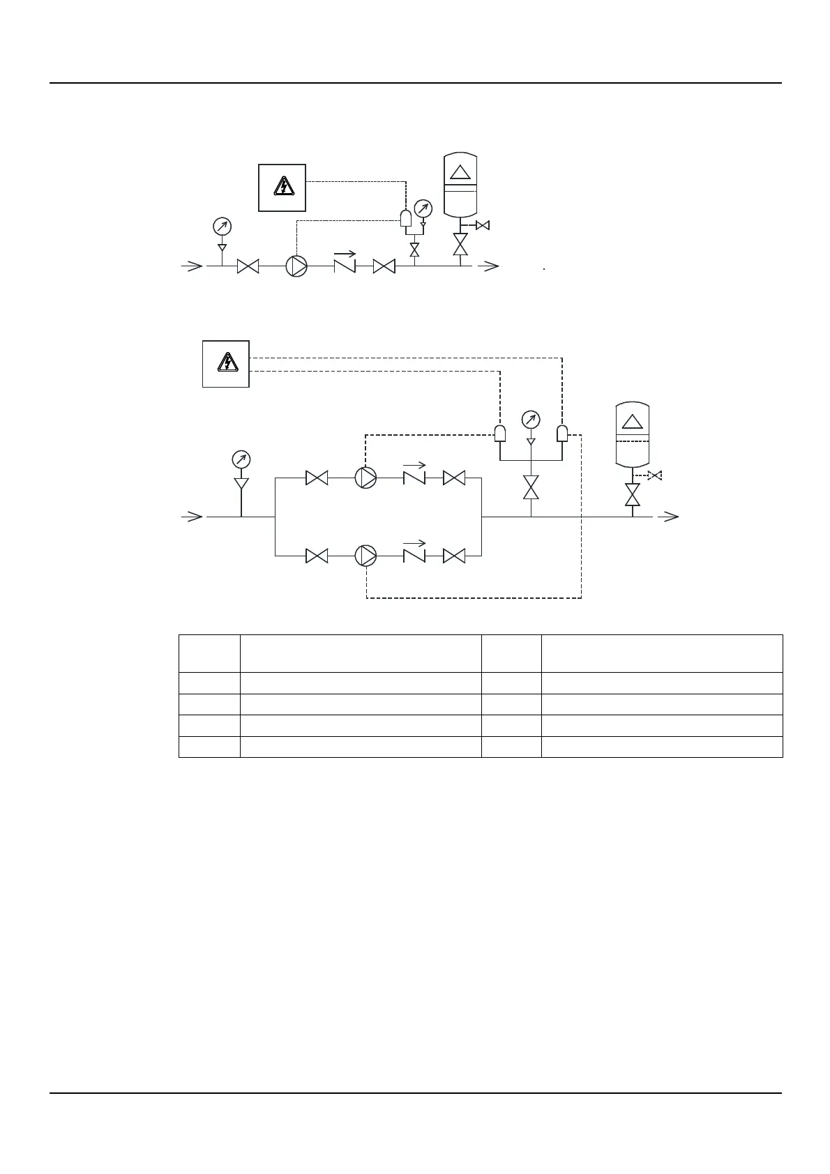
4.3.1 Guidelines for hydraulic connection
Refer to the representative hydraulic diagrams; see the figures below.
Figure 1: Installation with single pump unit
Figure 2: Installation of the booster set
Diaphragm pressure tank
≥
24 l (6.3 US gal)
1. Remove any welding residues, deposits and impurities in the pipes that could damage the
unit.
2. Install an on-off valve between the piping and the unit.
3. Install an on-off valve on the suction side and another on the delivery side of the pump unit.
4. Install a check valve between the unit and the pump unit.
5. Install a pressure gauge for the unit.
6. Install one or more diaphragm expansion tanks to limit the number of starts of the pump
unit.
Genyop_M0025_A_sc
4
1
5 4
4
8
2
7
6
7
4
3
Genyop_M0026_A_sc
4
1
5
4
4
1
5
4
4
8
2
3
4
O
U
T
IN
IN
OUT
7
7
6
6