

D
dflemingSep 12, 2025
What causes noise inside the disc tray of my Yamaha CD Player?
- MMichael Soto Jr.Sep 12, 2025
If you're hearing noise from inside the disc tray of your Yamaha CD Player, the disc might be warped. Try replacing the disc.
What causes noise inside the disc tray of my Yamaha CD Player?
If you're hearing noise from inside the disc tray of your Yamaha CD Player, the disc might be warped. Try replacing the disc.
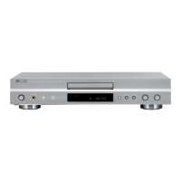
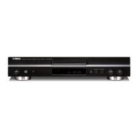
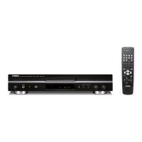
Why is there no sound from the headphones on my Yamaha CDX-596 or CDX-496?
If you're not getting any sound from the headphones on your Yamaha CDX-596 or CDX-496, check that the – OUTPUT LEVEL + buttons are not set to the minimum. Adjust the volume using these buttons.
Details on critical components requiring exact specification replacements.
Procedure for measuring leakage current to ensure safety during servicing.
Safety guidelines for preventing eye injury from laser radiation during servicing.
Notice regarding hazardous chemical content in product materials and safe handling.
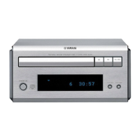
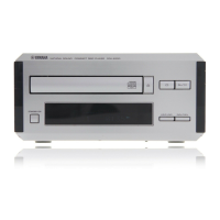
Physical dimensions and weight of the product.
Identification of main printed circuit board components and their locations.
Steps to remove the top cover of the unit.
Steps to remove the front panel assembly.
Steps to remove the CD mechanism unit.
Steps to remove the disc tray unit.
Steps to remove the optical pick-up head assembly.
Procedure to enter and activate the test mode for diagnostics.
Functions of the front panel keys when the unit is in test mode.
Functions of the remote control transmitter keys in test mode.
List of error codes and their corresponding descriptions.
Troubleshooting guides for specific error codes.
Troubleshooting steps for tray operation issues.
Troubleshooting for audio playback problems.
Troubleshooting steps when the unit acts like no disc is present.
Troubleshooting for audio skipping or playback interruptions.
Troubleshooting when search functions do not work correctly.
Pin assignments for display components.
Grid layout and assignments for display segments.
Anode connection details for display elements.
Detailed data and pinout for IC3, the Signal Processor Controller.
Overview of the system control functions of IC300.
Component layout for the main printed circuit board (foil side).
Component layout for the main printed circuit board (foil side).
Component layout for the main printed circuit board (foil side).
Component layout for the main printed circuit board (foil side).
Component layout for the main printed circuit board (foil side).
Component layout for the main printed circuit board (foil side).
Block diagram and details for the digital servo head amplifier IC.
Block diagram and details for the PU driver IC.
Block diagram and details for dual op-amp ICs.
Block diagram and details for dual op-amp IC.
Block diagram and details for the constant-voltage tracking supply IC.
Block diagram and details for the EEPROM IC.
Analysis of critical signal waveforms at various test points.
List of electrical components with part numbers and descriptions.
Schematic diagram of the remote control transmitter.
| Type | CD Player |
|---|---|
| Disc formats | CD, CD-R, CD-RW |
| Frequency Response | 2 Hz - 20 kHz |
| Dynamic Range | 100 dB |
| Output Level / Voltage | 2.0 V |
| Power Consumption | 15 W |
| Digital Outputs | Optical |